Introduction
I designed and built a 3D-printed enclosure for an ESP32 4-channel relay module to control low-power devices in my garage.
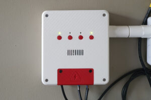
The enclosure included DIY PCB mounted on the front panel, equipped with buttons to manually control each relay and LEDs to indicate the status of each channel. Additionally, I designed an optional front panel that allows for the integration of I2C sensors for environmental monitoring.
I used ESPHome firmware for smooth integration with Home Assistant to complete control it with automation and synchronize with other devices in my home.
Component List

3D PRINT PARTS
ELECTRONIC COMPONENTS
TOOLS, SUPPLY, AND FASTENING
- M3 x 20mm Flat Head Screws (X4): Aliexpress
- M3 x 8mm Socket Head Screws (X4): Aliexpress
- M3xD5xL4 Brass Hot Melt Insert Nuts (X6): Aliexpress
- M1.5 Self-Tap Screw (x8): Aliexpress
FILAMENT USE IN THIS PROJECT
- eSun PLA+: Aliexpress
- eSun PETG: Aliexpress
WARNING:
This project involves working with AC power, which can be dangerous and potentially lethal if proper safety precautions are not taken.
Please ensure that you have a solid understanding of electrical safety before attempting this project. If you are unsure or uncomfortable working with AC power, please seek the assistance of a qualified electrician.
Always disconnect the power source and discharge any capacitors before working on any electrical circuit. Failure to take appropriate safety measures can result in serious injury or death.
ESP32 – 4X Relay module
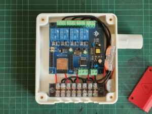
I chose this bare board instead of a ready-made solution like the Sonoff 4CH, which can be hacked to use ESPHome firmware. This custom build provides greater flexibility, allowing me to connect additional sensors and expand functionality with ease.
This ESP32 4-channel relay module is based on the ESP32-WROOM-32E (4Mb Flash). It offers plenty of GPIO pins, similar to other ESP32 development boards, making it easy to connect various sensors and peripherals. This flexibility enables custom features and future upgrades.
Additionally, the board supports multiple power input options, accepting both AC and DC power. Since I’m using AC power for all relay channels, powering the module directly with AC simplifies the wiring setup.

ESP32 Relay X4 Specifications
- ESP32 Chip: ESP32-WROOM-32E (4Mb Flash)
- Program download: UART (TX,RX,GND)
- Power supply voltage AC120-220V., DC5-30V.
- Onboard I/O Pin:
- GPIO32 → Relay1
- GPIO33 → Relay2
- GPIO25 → Relay3
- GPIO26 → Relay4
- GPIO23 → LED0
- GPIO0 → BUTTON
- Output Relay: 4 Channel (NO and NC)
- Board Size: 93×87 mm.
- Weight: 92 g.
AC Wiring
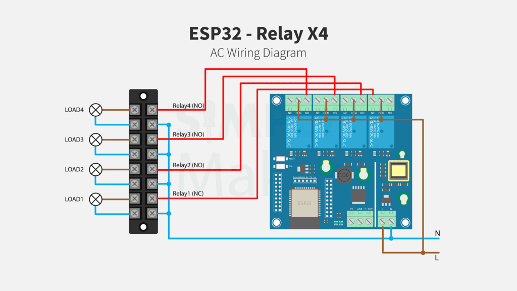
For the main power line, I used 2 Sq.MM wire and lever connectors to easily split the line into the relay ports and the barrier screw terminal.
Note:
For my use case, I connected Relay 1 to an oxygen pump and wanted to ensure it remains ON even if the module disconnects or becomes unavailable. To achieve this, I wired it to the Normally Closed (NC) terminal. However, this setup inverts the relay status LED behavior (Pump ON → Relay OFF → LED OFF). To correctly display the status (Pump ON → Relay OFF → LED ON), I used a separate GPIO pin for the LED, which I will explain in the next section.
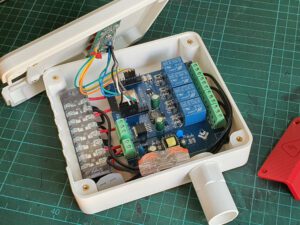
GPIO Wiring
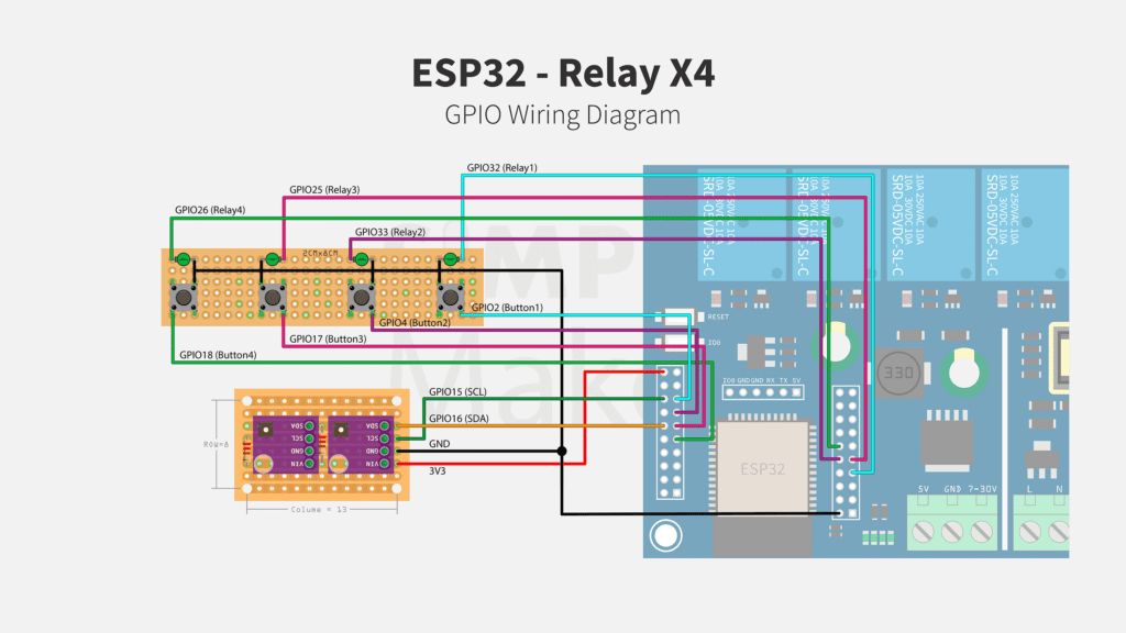
I connected status LEDs directly to each relay output pin, which also connects to the onboard status LEDs, eliminating the need for additional resistors. However, if you use different GPIO pins, you must add a current-limiting resistor.
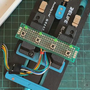
For easy assembly, the LEDs and buttons can be mounted on a 2 x 8 cm prototype board and secure to the front cover using M1.5×8 plastic self-tapping screws.
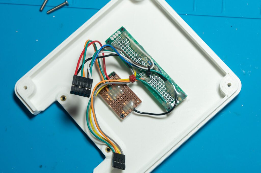
I also designed an alternative front cover with extra slots to mount I2C sensors. The sensors are placed on a stripboard (cut down to 8 rows x 13 columns) with 2mm mounting holes drilled in all four corners. To ensure reliable I2C communication, I added 4.7kΩ pull-up resistors to the SDA and SCL pins.
Flash ESPHome firmware
To flash the firmware, you’ll need a USB to UART serial converter. Follow the wiring diagram to connect the module properly. Ensure the serial converter is set to 3.3V mode to avoid damaging the ESP32.
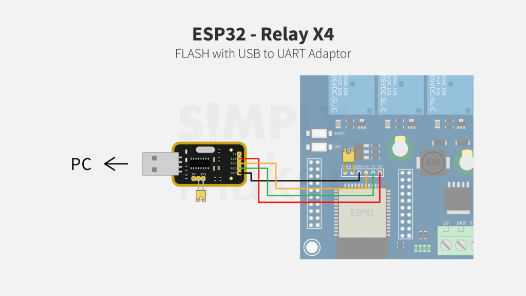
Prepare the ESP32 for Flashing:
- Connect TX on the converter to RX on the ESP32 module.
- Connect RX on the converter to TX on the ESP32 module.
- Connect GND to GND.
- Connect 3V3 pin to 5V on the ESP32.
- Place a jumper between IO0 and GND—this puts the ESP32 into flashing mode.

ESPHome YAML
Below is the complete ESPHome YAML configuration for this module. You can modify it based on your specific setup and preferences.
In this configuration, each relay is mapped to a specific GPIO pin, allowing manual control via onboard buttons and status indication through LEDs.
Relay and LED Configuration
output:
  - platform: gpio
    pin: GPIO32
    id: relay_pin_1
  - platform: gpio
    pin: GPIO33
    id: relay_pin_2
  - platform: gpio
    pin: GPIO25
    id: relay_pin_3
  - platform: gpio
    pin: GPIO26
    id: relay_pin_4
  # LED for RELAY1 (NC)
  - id: relay1_led_out
    platform: gpio
    pin:
      number: GPIO27
      inverted: False
      mode:
        output: True
        pullup: False
Switch and Light Configuration
switch:
  # NC (Normally Closed)
  - platform: output
    id: relay_1
    name: "Relay 1"
    output: relay_pin_1
    on_turn_on:
      - light.turn_off: relay1_led
    on_turn_off:
      - light.turn_on: relay1_led
  # NO (Normally Open)
  - platform: output
    id: relay_2
    name: "Relay 2"
    output: relay_pin_2
  - platform: output
    id: relay_3
    name: "Relay 3"
    output: relay_pin_3
  - platform: output
    id: relay_4
    name: "Relay 4"
    output: relay_pin_4

light:
  #For Relay1 (NC)
  - platform: binary
    name: "Relay1 LED"
    id: relay1_led
    output: relay1_led_out
    internal: False
Button Configuration
binary_sensor:
  - platform: gpio
    name: "Button 1"
    id: button1
    pin:
      number: GPIO2
      mode:
        input: true
        pullup: true
    on_press:
      then:
        - switch.toggle: relay_1
    internal: True
    filters:
      - invert:
  - platform: gpio
    name: "Button 2"
    id: button2
    pin:
      number: GPIO4
      mode:
        input: true
        pullup: true
    on_press:
      then:
        - switch.toggle: relay_2
    internal: True
    filters:
      - invert:
  - platform: gpio
    name: "Button 3"
    id: button3
    pin:
      number: GPIO17
      mode:
        input: true
        pullup: true
    on_press:
      then:
        - switch.toggle: relay_3
    internal: True
    filters:
      - invert:
  - platform: gpio
    name: "Button 4"
    id: button4
    pin:
      number: GPIO18
      mode:
        input: true
        pullup: true
    on_press:
      then:
        - switch.toggle: relay_4
    internal: True
    filters:
      - invert:
Optional I2C Sensors Configuration
An I2C sensor module can be added to monitor environmental conditions. In this example, I’m using a BME280 (5V) sensor to measure temperature, humidity, and air pressure, along with an SGP30 for monitor TVOC and CO₂ levels.
Below is the ESPHome YAML configuration for integrating these I2C sensors:
i2c:
  scl: GPIO15
  sda: GPIO16
sensor:
  - platform: bme280_i2c
    address: 0x76
    temperature:
      name: "Fish Tank Temperature"
      id: bme_temp
    pressure:
      name: "Fish Tank Pressure"
      id: bme_pres
    humidity:
      name: "Fish Tank Humidity"
      id: bme_humid
    update_interval: 90s
  - platform: sgp30
    address: 0x58
    eco2:
      name: "Fish Tank eCO2"
      accuracy_decimals: 1
      filters:
      - sliding_window_moving_average:
          window_size: 30
          send_every: 30
    tvoc:
      name: "Fish Tank TVOC"
      accuracy_decimals: 1
      filters:
      - sliding_window_moving_average:
          window_size: 30
          send_every: 30
    store_baseline: yes
    update_interval: 1s
    compensation:
      humidity_source: bme_humid
      temperature_source: bme_temp
Conclusion
With this ESP32 4-channel relay module, you now have a flexible and expandable solution for controlling multiple devices in your smart home setup. By integrating ESPHome, the module seamlessly connects with Home Assistant, allowing for easy automation and remote control.
The custom enclosure provides a clean and organized installation, and adding optional I2C sensors enhances your system with valuable environmental monitoring capabilities.
I hope this guide helps you in setting up your own smart relay module. If you have any questions or improvements, feel free to share!
This content is intended to share ideas and inspire DIY projects. While we’ve taken care to ensure accuracy, we are not liable for any losses, damages, or injuries that may occur from following these instructions or using the information provided. Please proceed with caution, and always follow safety guidelines when working on your projects.
Disclaimer


Thanks for the write up! It’s been helpful for my current project. Just FYI, many of your links to ali express are either dead or all link to the same item.
Glad to hear it was helpful, and thanks for pointing that out!
I’ve updated all the links.