
Introduction
If you do a lot of soldering, you know how important it is to keep yourself safe from harmful fumes. Our fume extractor is designed to do just that. Because it has a built-in buck convertor, This fume extractor can accept a wide range of power inputs, the working voltage is around 10 to 23 volts

I’ve designed it to use with my DIY soldering station so it can share input from a single Makita battery. But it can also be used with any power supply. I also include an extra DC port for forwarding the input to other DC devices and also an LCD voltmeter that lets you monitor the primary input voltage.
This is particularly useful to save space and reduce clutter on your workbench. You can use it to power portable LED lights, test a module, power a test circuit and so on.
And if you are using portable soldering iron like the popular TS100 mini soldering iron you can share the power supply by connecting the soldering iron power supply to the extractor and then plugging the soldering iron into the extra DC port. Moreover, I’ve included a USB-C power delivery input. With a suitable USB power delivery charger, you can also power the soldering iron with it.

This fume extractor also featured a built-in carbon filter bay. You can quickly and easily replace the filter with a simple latched door mechanism. I also included a detachable hood that uses small magnets to hold it securely to the case. This allows it to be easy to attach and remove as needed.
At the bottom of the case, I included a slot for a 4-centimetre magnet that let it attach to a steel base and some holes for M4 hot melt insert nuts for an additional attachment.
To make it even more versatile, I’m working on its add-on battery pack. So stay tuned and subscribe to my youtube channel to make sure you don’t miss any updates.
► SUBSCRIBE TO MY CHANNEL: https://shorturl.at/bjrEK
Material List

3D PRINT PARTS
- 120mm Soldering Fume Extractor: Thingiverse.com | Printable.com
COMPONENTS FOR THIS PROJECT
- PD 3.0 Trigger Board (15v/20v): Aliexpress | Shopee Thailand
- Mini DC-DC 2A Step-Down Converter: Aliexpress | Shopee Thailand
- 0.36” LCD voltmeter: Aliexpress | Shopee Thailand
- KCD1 Rocker Switch: Aliexpress | Shopee Thailand
- DC Power Socket 5.5×2.1mm – x2: Aliexpress | Shopee Thailand
- 2P JST-SM connector: Aliexpress | Shopee Thailand
- 1N4007 Diode: Aliexpress | Shopee Thailand
- 3A Screw terminal strip: Aliexpress | Shopee Thailand
- Activated Carbon Air Filter: Aliexpress | Shopee Thailand
- 5x3mm neodymium magnets – x4: Aliexpress | Shopee Thailand
SUPPLY AND FASTENING
- Brass Hot Melt Inset Nuts SL-type (M3xD5xL4) – x2: Aliexpress
- Brass Hot Melt Inset Nuts SL-type (M4xD6xL5) – x6: Aliexpress
- Socket Head M4 – 50mm – x2:
- Socket Head M4 – 35mm – x2:
- Button Head M4 – 10mm – x2:
- Flat Head M3 – 35mm – x2:
- Button Head M3 – 10mm – x2:
- Button Head M3 – 5mm -x2:
TOOL I USE
- ARROWMAX Electric Cordless Screwdriver (SES): Aliexpress
- T12-TR Portable Soldering Iron: Aliexpress
- 100W USB-C Charger: Aliexpress
- DIY Makita T12 Soldering Station:
FILAMENT USE IN THIS PROJECT
- eSun PETG: Aliexpress | Shopee Thailand
- eSun PLA+: Aliexpress | Shopee Thailand
► SUBSCRIBE TO SIMPLY MAKER YOUTUBE CHANNEL:

How to Make
Begin by inserting an M4 hot melt insert nut into the fan case. For this project, I use M4 nuts with a diameter of 6 millimetres and a height of 5 millimetres. There are four spots on the centre part and two on the back cover.
Next, we will replace the fan connector with a 2P JST-SM connector. The fan I have has 3 pins Molex connector. Pin 1 is the ground wire, pin 2 on the centre is V+ and the last pin is for speed control.
Cutting the fan wire to the appropriate length and crimp the female connector to the fan wires, making sure to pay attention to the pin orientation to prevent the wires from twisting.
Wiring Electronic Components

Step-Down Converter
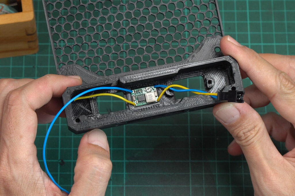
Prepare the buck converter, and use a voltmeter to make sure that the output voltage is match the fan you’re using. Solder the wires to the converter’s input and output. For the output, we will use wires with a crimped male JST connector. After finish, use VHB tape to attach it to provide a slot on the fan case.
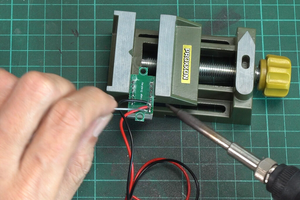
0.36″ LCD Voltmeter
For this project, I will use a 0.36″ LCD voltmeter. If the voltmeter you got has 3 wires, you can cut off the yellow wire and connect it to V+, to reduce wire clutter. Assemble it to the case with 5mm button head M3 screws.
KCD1 Rocker Switch
Connect a wire to one of the rocker switch pins, and insert it into the case. Connect another pin with the wire from the buck converter’s input positive.

USB-C Power Delivery Trigger Board

The PD trigger board I use is PDC004. It has a fixed output voltage which you can choose while purchasing. Generally, the board is separated into two versions, 9v/12v and 15v/20v. You can switch between each voltage with a solder jumper. The board I have is 15 volts so I just bridge the jumper to get 20 volts.
I also add a 1N4007 diode to the board output for extra protection. Connect one of the diode pins to the board to OUT+, and make sure that the grey strip is facing out. Then connect the positive wire to another pin. After finish, the wiring, use VHB tape to attach it to the case.
5.5×2.1mm DC Sockets
After soldering the wire to the DC socket’s pins. Mount them to the case by placing the nut into the provided slot and screwing the DC socket in. Use a plier to tighten it firmly.
To easily join all the wires together, I recommend to uses a screw terminal block. Just cut two blocks from the terminal strip. Then insert the twisted wires from each side to the terminal block and tighten the screws. After finish, use some cable ties to keep it in place.
Assemble the Case

Add the printed shimmer to all corners of the PC fan. This shimmer will prevent the case and the fan from bending when you tighten it with screws. Then mount the fan to the front part and connect the fan connector to the buck converter board.
Use two 35mm socket head M4 screws to secure the lower corner of the fan to the middle 3D printed part. Attach the back cover and use two 55mm socket head M4 screws to connect it with the latch and the front and middle parts. Firmly tighten both screws to allow the latch to open and close freely.

Use 10mm M3 and M4 to secure the back cover and finally, use 35mm flat head M3 to secure the front corner of the case.
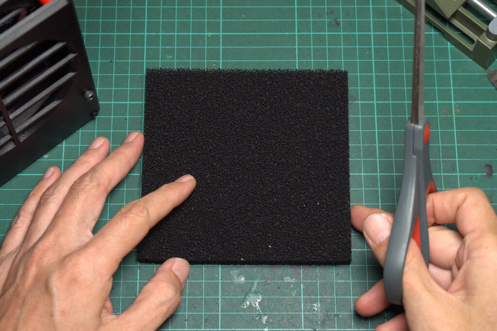
Carbon Filter
Cut the carbon filter sheet to about 120mm by 120mm. I use a 1 centimetre thick filter. Then insert it into the carbon filter bay.
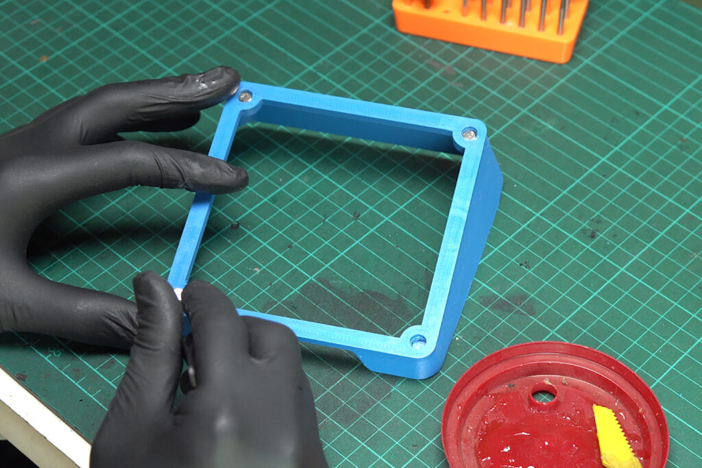
Detachable Magnetic Hood
Use epoxy glue to attach 5×3 mm diameter neodymium magnets to provide holes on each corner of the 3D-printed hood.
Final Note
A few cautions when using this fume extractor.
- Please note that the module we use to regulate the voltage for the fan is a step-down converter. To ensure that the fan will run at optimal speed. Make sure that the power supply you’re using can deliver a voltage higher than the voltage required by the fan you’re using.
And if you’re using a USB-C port make sure that the charger support power delivery that can output more than a regular USB charger. - It’s important to remember that the extra DC outlets are not regulated circuits. So, before you plug any other device into them, make sure that it can accept the voltage from the main input. You can easily monitor the input voltage with the built-in LCD voltmeter.
DISCLAIMER: This content, video and description may contain affiliate links that support our channel. We are not responsible for any losses, damage, or injury in connection with the use of our content.


Thanks for sharing. I’m excited to give this a try. Just wanted to give you a heads up that the product link for “3A Screw terminal strip” on AliExpress goes to the 100W USB C charger.
Thankyou so much for letting me know. Already fix that.
Thanks!!
I am running into the same problem. Its not a big deal, but it persists.
Heads up: The link for the “3A Screw terminal strip” goes to the USB-C 100 Watt Charger
Ich Frage mich, wo die zwei M3 Einschmelzmuttern hin gehören ?
Ansonsten ein absolut gelungenes Design.
Löste meinbm
The M3 hot melt insert nuts are for the bottom corner M3 screws. In the video I just taps into the plastic.
Silly question, but what 120mm fan did you use, does it matter the thickness of the fan?
It’s 25mm thickness.