Introduction
Today I like to upgrade an original Tivoli Audio Model One with a custom 3D print Bluetooth module, Wifi Smart plug, and 75-Ohm antenna. The upgrade allows you to enjoy wireless music from your old device and make it more convenient to use.

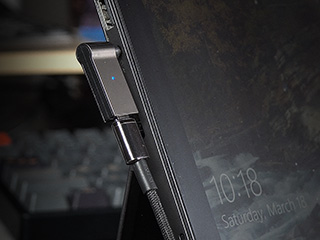
The better way to add a Bluetooth audio receiver module to the vintage active speaker or any audio system that uses a DC power supply is a custom enclosure. With a custom enclosure, you can simplify the setup by integrating the power source and the external Bluetooth into a single module. This way, you can achieve a neater wiring setup without worrying about finding an additional power source.
The Tivoli Audio Model One can use both AC and DC as the power input and its auxiliary port is located next to the DC jack. So, I’ve designed a custom enclosure specifically for it, which can be directly attached to its back without requiring any additional wiring.

For this project convert DC 12 volts to DC 5 volts, I will be using a fixed input isolator instead of a buck converter. Initially, I designed the circuit using a mini buck converter, but during testing, I discovered that it produced some ground loop noise. Although this noise is barely noticeable and can only be heard at maximum volume with no input, it can still be quite annoying. However, this problem does not occur when using a separate power supply
If your system requires a different input voltage, you can use a buck converter to convert from a higher DC voltage to 5 volts. Then connect a 5 volts to 5 volts input isolator between the buck converter and the Bluetooth board input.

Material List

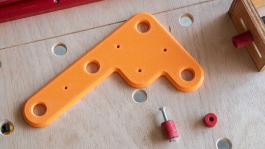
3D PRINT PARTS
COMPONENTS FOR THIS PROJECT
- DIY Bluetooth Receiver Module (VH-314 or XFW-BT): Aliexpress | Shopee Thailand
- B1205S-1W fixed voltage ground isolator: Aliexpress | Shopee Thailand
- 6mm SPDT Slide Switch (2 Positions 3 Poles): Aliexpress | Shopee Thailand
- DC Power Socket 5.5×2.1mm: Aliexpress | Shopee Thailand
- DC Power Jack 5.5×2.1mm: Aliexpress | Shopee Thailand
- 3.5mm 3 Pole Audio Jack: Aliexpress | Shopee Thailand
Optional Components
- 1N4007 Diode 1A: Aliexpress | Shopee Thailand
- Tuya WiFi Smart Plug 10A: Aliexpress | Shopee Thailand
- 75-Ohm FM Indoor Antenna 7 sections 75 cm: Aliexpress | Shopee Thailand
- Mini DC-DC 2A Step-Down Converter: Aliexpress | Shopee Thailand
- B0505S-1W fixed voltage ground isolator: Aliexpress | Shopee Thailand
- 5/16-24 Fine Thread Tap: Aliexpress | Shopee Thailand
- 12V 5A Power Supply: Aliexpress | Shopee Thailand
SUPPLY AND FASTENING
- Brass Hot Melt Inset Nuts SL-type (M3xD5xL4): Aliexpress
- M3 x 12mm Button Head Screws (X3):
- M3 x 20mm Button Head Screws (X1):
- M2.5 x 5mm Button Head Screws (X2):
- M2 x 5mm Button Head Screws (X2):
- Shield wire and 24 AWG wires:
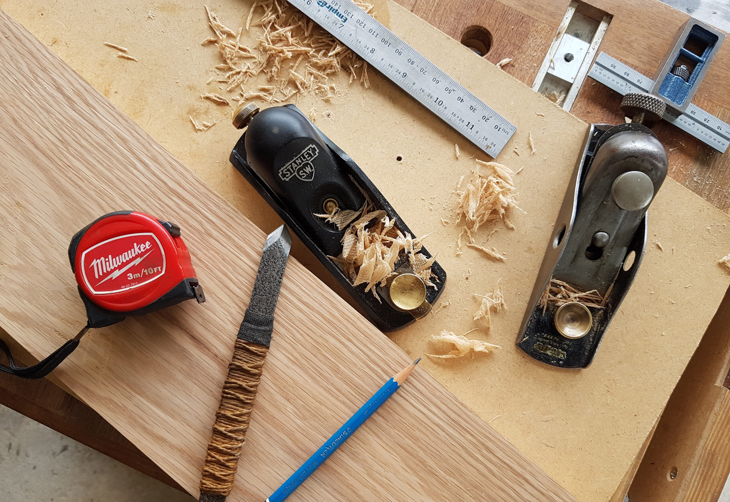
TOOL I USE
- UNI-T UT89X Digital Multimeter: Aliexpress | Shopee Thailand
- ARROWMAX Electric Cordless Screwdriver (SES): Aliexpress
- PG8018LCD Electronic Hot Air Gun: Aliexpress
- T12-TR Portable Soldering Iron: Aliexpress
- DIY Makita T12 Soldering Station:

FILAMENT USE IN THIS PROJECT
- eSun PLA+: Aliexpress | Shopee Thailand

The bluetooth audio receiver board we’re working with is quite popular. It has many versions and manufacturers producing it. In my case, I purchased two of these boards from the same supplier and the same listing but at different times. The board on the left, which has the default Bluetooth name of VH-314, is the first one I purchased, while the other one is named XFW-BT.
Upon using these boards, I noticed that the main difference between them was the status interface. The XFW-BT board has a sound notification when it’s powered on and is ready to connect, and the LED blinks rapidly. It also has a notification sound when a device is successfully connected, and the LED remains on. During music playback, the LED blinks slowly. On the other hand, the VH-314 board has no notification sound and the LED always blinks rapidly when powered on. This difference could be due to varying software versions.
Note About the Bluetooth board:
► SUBSCRIBE TO THE CHANNEL: http://shorturl.at/gikA4
How to Make
First, we will use the 5/16 hand tap tool with a 24-fine thread to create threads for the DC jack and 3.5-millimetre jack. Both have the same diameter and thread. Tap the thread to both holes on the connector part.

Next, use a soldering iron to insert M3 heat-insert nuts into the 3D-printed parts. These nuts will need to be inserted in one spot on the connector part, and three spots on the main part. Then apply a thin layer of epoxy glue to the connector part.
Attach the connector part to the main part, making sure they fit together snugly. Clamp the two parts together using a clamp or tape to hold them in place while the epoxy sets.
In the next step, we will insert a magnet into the enclosure’s back. The magnet will be attached to a screw on the back of the speaker for extra holding. This is totally optional.
Apply epoxy glue to a 5 by 5 magnet. In order to insert the magnet into the enclosure. Attached the magnet to a bench vice and use a large screw nut to support the other side of the enclosure. Align the magnet to the provided hole and press it in.

Next, we’re going to work with connector parts. Start with the 5.5mm DC jack, and separate the DC jack from its shell. Trim off the negative pin connector to shorten it for a bit. Then smooth the cut edge with a metal file.
You need two wires for each pin. Twisted 2 wires together, and tin it with some solder. Then connect them to both the positive and negative pins of the DC connector jack. Once all the wires are connected. Then cover all the connections with some shrink tubes.

Our next step will be working with a 3.5-millimetre audio jack. Separate the head of the audio jack from the shell. There are 3 pins on the audio jack output. The tip is for the left channels, the centre ring is for the right channel and the sleeve is for the ground.

If you are not sure about the pinout please use a multimeter to double-check it. I use a 24 AWG shield wire for the audio jack. Solder the red one to the right channel pin. The white one connects to the left channel and the unshielded wire goes to the ground pin. After finishing, the connections, cover them with some shrink tubes.
To assemble the audio jacks into the enclosure begins by inserting their connected wires into the top holes on the connector parts. Then carefully screw them into the tapped holes on the case. Repeat the process on another hole with the DC jack.
Now let’s continue with the enclosure. Attach the slide switch to the enclosure with M2.5 screws. The next step is to attach the DC socket to the enclosure cover. Secure it in place using the provided screw nut. Use a wrench to tighten it up.

Now it’s time to connect the electronic components to the connectors according to this wiring diagram. Let’s begin by wiring the input. Solder a positive and negative wire from the DC jack to the DC socket. Make sure that the positive wire is connected to the centre pin.

Next, we will connect the 1N4007 diode to the positive wire from the DC jack. Make sure that the strip mark on the diode is facing outward. Then insert a shrink tube into the wire and connected it to the slide switch. Then cover the diode with the shrink tube.
Now we will connect a wire to the B1205S-1W ground isolator. The isolator has four pins, pins 1 and 2 are for the input and the other two are for the output. Pin 1 is marked by a grey dot. Connect a short positive wire to pin 2, this is input positive. Then connect another two wires, that will go to the Bluetooth board, to pin 3 and pin 4.
Insert a shrink tube into the ground wire from the DC jack and connect it to pin 1. Then connect a wire from the second pin to the slide switch.

Once you’ve finished all the wiring, apply some heat to all the heat-shrink tubes. However, to prevent any damage to the 3D-printed enclosure, you may need to remove the slide switch before applying the heat.
Insert the Bluetooth board into the enclosure and secure it with M2 screws. Apply a VHB tape to the isolator and attach it to the enclosure.
Now it’s time to start wiring the Bluetooth board. Begin by soldering the DC output from the isolator to the board input.
Then connect the audio wire to the audio output pin. You can also solder the ground wire to the metal part on the 3.5-millimetres audio socket.
I also cover the soldered joints with some hot melt glue to provide extra strength and shield them from accidentally being shorted with other wires.

After completing the wiring, this is what the enclosure should look like. Now, you can close the cover and secure it with M3 screws.
Use the 20-millimetre screw for the top left hole and use the three 12-millimetre screws for the remaining holes to secure the cover in place.
To make it more convenient to use, I added a smart wifi outlet in order to control it with the Google Home app. I will leave the speaker’s main switch to the auxiliary input and turn the switch on the Bluetooth module to the On position.

This way, whenever I turn on the speaker using the Google Home app, it automatically connects to the paired device.
Conclusion
In conclusion, upgrading the Tivoli Audio Model One with a custom 3D-printed Bluetooth module, WiFi smart plug, and 75-Ohm antenna significantly enhances its functionality and usability. The project provides a modern touch to the vintage speaker, allowing for wireless music streaming and smart home integration.
Overall I am really satisfied with the result and sound of this module. This upgrade combines practicality with modern technology, extending the life and utility of the classic Tivoli Audio Model One.
► SUBSCRIBE TO THE CHANNEL: http://shorturl.at/gikA4
► FACEBOOK: https://www.facebook.com/simplymakerth
► INSTAGRAM: https://www.instagram.com/simplymakerth
DISCLAIMER: This video and description contain affiliate links that support our channel. We are not responsible for any losses, damage, or injury in connection with the use of our content.


Awesome !
I like the way to modernize the Tivoli Audio Model One which has a great sound.
Any suggestion how to pair a second Tivoli Audio speaker to convert a Model One into a stereo system?
Sorry but, I’ve no idea how to connect the second speaker.
Hello. What a great solution. Now that all the parts are home, I realized that Model one and two are different. Are you able to make one that fits model two?
Any tips for doing this as an internal mod? The hardest bits for me are building the enclosure (lack of printer and tap)
Sorry, I never open it up so I have no idea about internal mod.
Since I don’t have a 3D printer etc I’m thinking of a simpler hybrid internal-external mod, and I’d appreciate your opinion. The Bluetooth module you used can be purchased in a neat box which I would stick on the back of the unit.
I was thinking to draw power from the output of the mains transformer and using the ground isolator to bring it down to 5V. This would sit inside the box. I’d route the 5v power out through a hole and connect it to a micro-usb M to power the Bluetooth unit. Then I would just connect a M-M audio cable.
Questions:
* the transformer output is labelled 11.5V – is that an issue?
* what does the diode do? You list it as optional.
* Is a switch needed in order to allow radio to be used (otherwise the system is switched permanently to AUX)?