Introduction
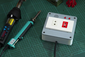
I recently reviewed this budget desoldering iron, and I was really impressed with its performance. However, it lacked a built-in switch, so I had to unplug it every time I wanted to turn it off. To fix this inconvenience, I designed a custom smart outlet to control the desoldering iron remotely.
With ESPHome, I can easily add more functions beyond simply turning it on or off. For example, I included a timer and notifications to let me know when the tool is warmed up and ready to use, as well as alerts if I leave it on for too long.

The best part is that you can customize all these functions to suit your specific needs. Additionally, I included a second outlet with a delayed turn-off function for my hot air gun, which needs to cool down before the power can be completely shut off.
Three Ways to Control Your Smart Outlet:
In addition to controlling the device through Home Assistant dashboard over Wi-Fi network. I’ve added a RF remote control and also physical buttons on the cover.
Personally, I prefer using the RF remote control. It allows me to manage my devices without needing to access my phone or computer. And I’ll be using the same remote control that I used in my previous DIY Wifi LED lamp project.
By including all the necessary functions in the firmware and providing physical controls, the device can operate independently with all its features even when there’s no network connection.
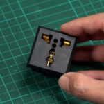
The AC socket I’ve used is a standard wall-mount socket commonly found in my region, but it might not be as popular elsewhere. For other regions, I’ve included an alternative cover designed to fit a panel mount AC socket for easier sourcing.
Please note that I haven’t tested this cover yet, so there might be some issues or adjustments needed.
Material List
3D PRINT PARTS
- Printables.com: Two Channels Smart Outlet Enclosure ESPHome and Home Assistant
- Thingiverse.com: https://www.thingiverse.com/thing:6133993
COMPONENTS FOR THIS PROJECT
- Wemos D1 Mini ESP8266: Aliexpress | Shopee Thailand
- Power Supply 5v 700ma: Aliexpress | Shopee Thailand
- 2 Channel Relay Module: Aliexpress | Shopee Thailand
- 433MHz RF Receiver Module (RX480-E): Aliexpress | Shopee Thailand
- RF Remote Control: Aliexpress | Shopee Thailand
- Prototype Board (2×8 and 3×7 cm): Aliexpress | Shopee Thailand
- KF301-2P Screw Terminal: Aliexpress | Shopee Thailand
- Active Buzzer 5v (9.3 mm): Aliexpress | Shopee Thailand
- 2N2222 NPN Transistor: Aliexpress | Shopee Thailand
- 47Ω & 2.2kΩ Resistor 1/4w: Aliexpress | Shopee Thailand
- 6×6 Tactile Push Button Switch (H. 6mm): Aliexpress | Shopee Thailand
- 3mm LED: Aliexpress | Shopee Thailand
- Universal AC Socket: Aliexpress | Shopee Thailand
ELECTRONIC SUPPLY AND FASTENING
- JST-XH2.54 Connector: Aliexpress | Shopee Thailand
- DuPont Connector (M20): Aliexpress | Shopee Thailand
- Pin Header 2.54 (Male & Female): Aliexpress | Shopee Thailand
- 18 AWG and 24 AWG wires: Aliexpress | Shopee Thailand
- M2 Self-tap screws: Aliexpress | Shopee Thailand
- 2-in 4-Out Quick Connector: Aliexpress | Shopee Thailand
- 90 Degree Foldable US Plug: Aliexpress | Shopee Thailand
- Brass Hot Melt Inset Nuts SL-type (M4xD6xL5) – x4: Aliexpress
- M4 x 10mm BHCS(x4):
- M4 x 10mm FHCS(x4):
- M3 x 15mm BHCS(x1):
- M3 x 8mm BHCS(x2):
- M2.5 x 8mm BHCS(x4):
TOOL I USE
- YIHUA 929D-V Desoldering Iron: Aliexpress
- 650W LCD Hot Air Gun: Aliexpress
- ARROWMAX Electric Cordless Screwdriver (SES): Aliexpress
- DIY 120 mm Soldering Fume Extractor:
- DIY Makita T12 Soldering Station:
FILAMENT USE IN THIS PROJECT
- eSun ABS+: Aliexpress | Shopee Thailand
- eSun PETG: Aliexpress | Shopee Thailand
- eSun PLA+: Aliexpress | Shopee Thailand
WARNING: This project involves working with AC power, which can be dangerous and potentially lethal if proper safety precautions are not taken. Please ensure that you have a solid understanding of electrical safety before attempting this project. If you are unsure or uncomfortable working with AC power, please seek the assistance of a qualified electrician. Always disconnect the power source and discharge any capacitors before working on any electrical circuit. Failure to take appropriate safety measures can result in serious injury or death.
For a more detailed visual guide on usage demonstration and assembly instructions, be sure to check out my YouTube video.
► SUBSCRIBE TO SIMPLY-MAKER YOUTUBE CHANNEL:
How to Make
Main Custom PCB
Starting with the main controller board. I use a 3 x 7cm Double-Sided perf board. The board consists of 10 rows and 24 columns. I use my jigsaw table to trim it down to 20 columns.
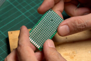
In the 3D printed part, I’ve included additional holes for mounting the PCB. I use 2 mm drill bit to drill a hole on the top right of the board. Because the final wiring was turning out to be messier than I expected. The middle hole might end up being obstructed by the wires. So it won’t be necessary to drill that particular hole.
Next, we’ll proceed to attach all the parts to the board and establish the necessary connections according to the provided schematic. To confirm that all the parts fit correctly, I recommended placing all the components on the board and marking their positions before starting the soldering.
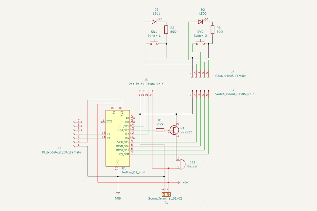
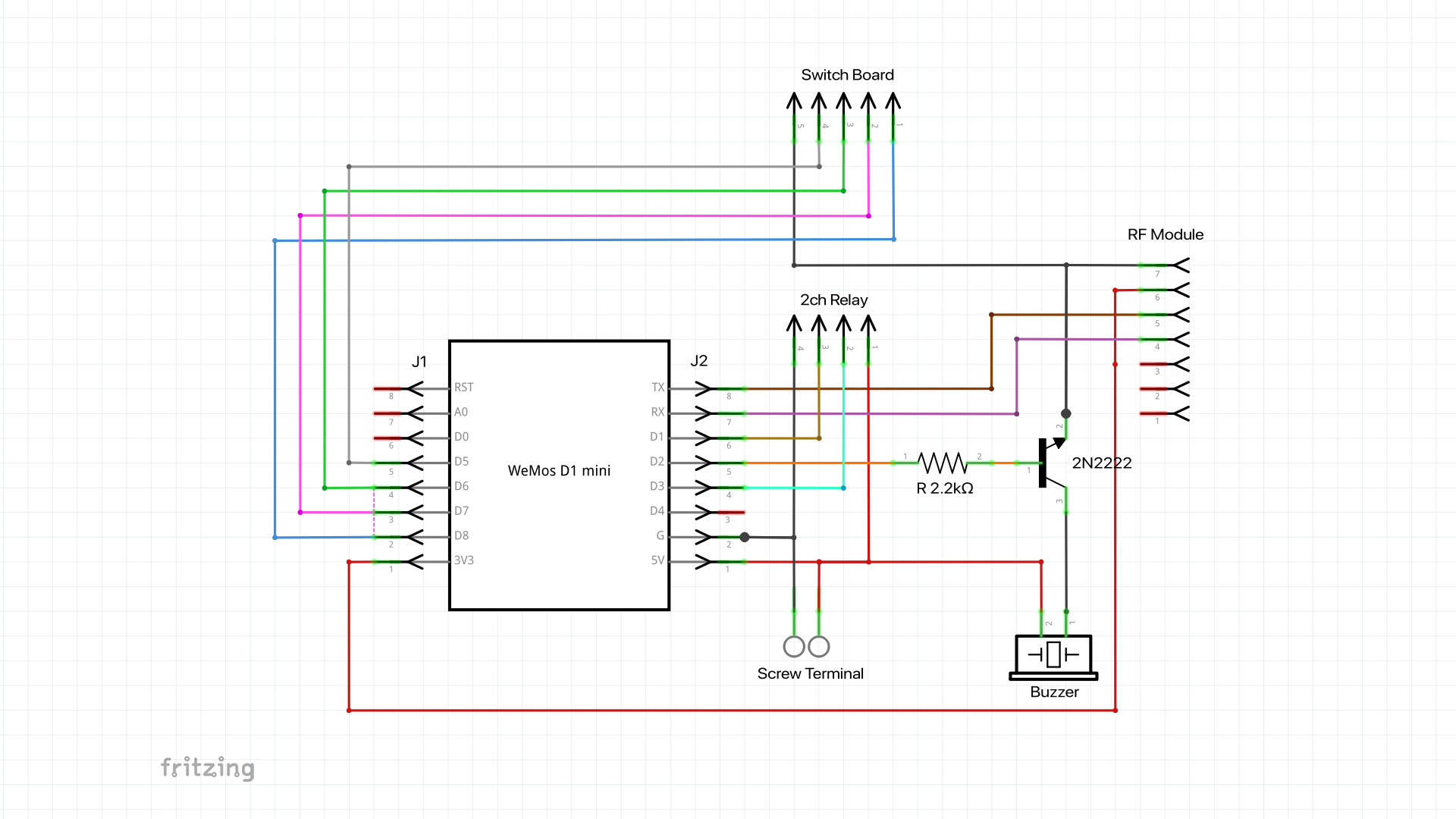
For the microprocessor, I use this D1 mini development board. It’s one of my favourite because of its compact size and plenty of GPIO pins. Because of its great popularity, there are a lot of libraries and tutorials available, making it easy to implement and find online assistance when needed.
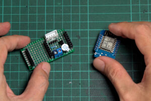
To connect the D1 mini to the perf board, I use the female pin headers that came with it. This is my preferred choice when there is sufficient space within the enclosure.
It provides convenience for future maintenance. I can easily detach the MCU board in case it needs a replacement or the need for firmware flashing by connecting it to a computer.
I also use a female pin header to connect to the RF module, so it can be easily to replace. I use a female pin header strip I got from Aliexpress. Since the RF module has 7 pins, so we’ll need to cut the pin header strip to the appropriate size.
RX-480E RF 433 MHz Receiver Module
To use the RF remote control, I use this 4 channels RF receiver module. It’s quite easy to use with the built-in learning feature. So it no need for an extra process to obtain the remote control codes for programming.
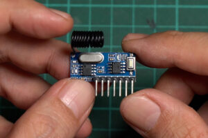
However, the application will be limited to 4 channels and not allow individual programming of each button.
During the pairing process, the module automatically assigns each button’s signal from the remote control to one of the output channels. And the assignments may not follow a sequential order.
Therefore, before connecting the module to the MCU, it’s necessary to identify the specific output pin corresponding to each button you wish to use.
While it has no issues using it with 4 button remote control. But when I try to use it with my 8 buttons controller, some buttons were skipped. Luckily, I need only 2 buttons for this project. With 4 buttons controller, I can use the other 2 with my LED lamp.
So, for this project, I just stick with the RX-480E module. (data sheet)
To identify the output pin, just connect the RF module to a breadboard and provide it with a 3.3-volt or 5-volt power supply. Begin by connecting the black probe of the multimeter to the ground. With the multimeter set to measure voltage, use the red probe to test the voltage from each output pin individually.
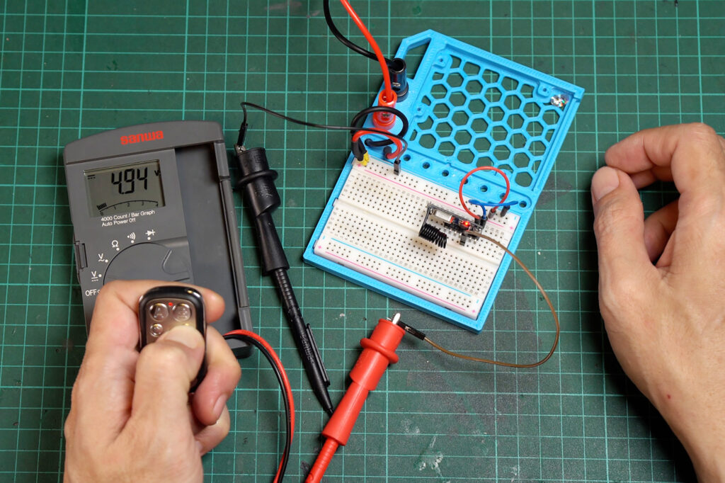
Then press and hold the remote control button you like to use. The output pin corresponding with the currently pressed button should read a similar voltage as the input power supply. The VT pin will output whenever the module receives matched RF signal. This pin can be used to generate a notification when the module has received data.
Front PCB
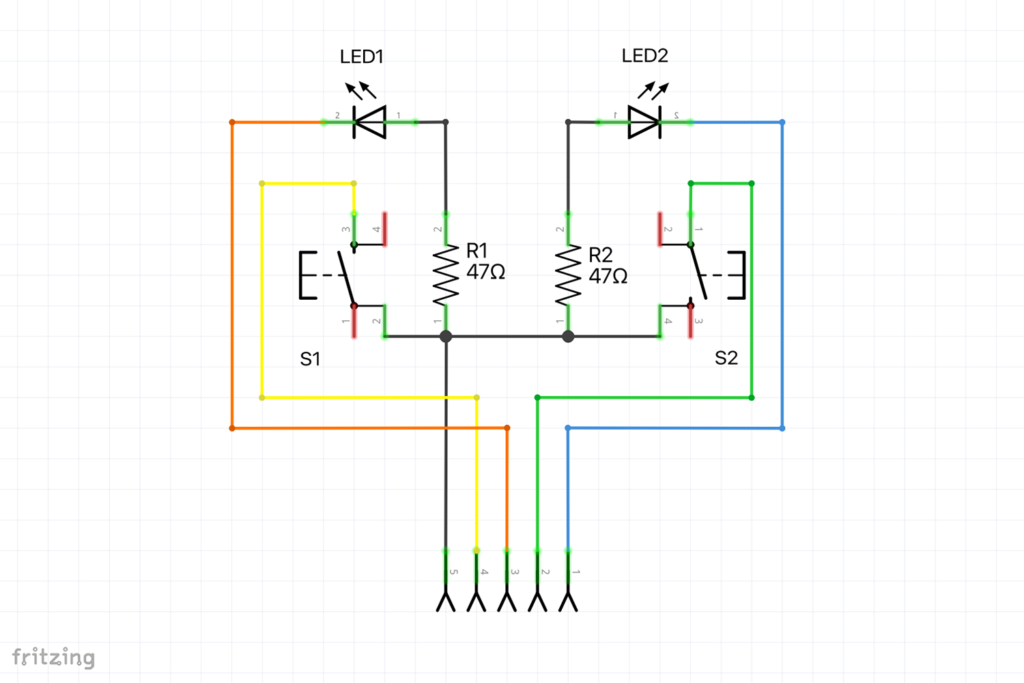
This PCB is where we house momentary switches for manual operation and LEDs to display the module’s status. I use a 2 by 8 centimetres double side perf board and cut it down to 14 columns.
After attaching all the components and connecting them according to the schematic, we need to solder wires to link them to the main PCB. I will use 5 pins JST XH connector for the connection.
ESPHome Firmware
Before proceeding further, it’s a good idea to flash the firmware to the ESP module and test it to ensure everything is functioning correctly.
To integrate the device with Home Assistant and enable control over Wi-Fi, I’ll be using the ESPHome firmware. There are tons of tutorials about installing and using Home Assistant with ESPhome, so I won’t dive into the details here.
Script Control Functions:
- RF button1 and Front Button1: For control the desoldering iron(outlet1). When turn on, the LED1 will blink and issue a beep sound every 1 minute to indicate the desoldering iron in warm-up time.
After 3 minutes it will issue 3 beeps and LED1 will stay on indicate that the desoldering iron is warmed up and ready to use. - RF button2 and Front Button2: For control the hot air gun(outlet2). When turn on, it simply turn on the outlet2 and LED2 will turn on.
When turn off, the LED2 will blink and delay for 4 minutes allow the hot air gun fan stay on and cool down the heater before cutting off the power. Double-Click to cancel the timer and immediate power-off.
You can adjust the warm-up time and delay-off time in the globals: section of the YAML configuration.
In the “esp8266” section change the “board” setting to “d1_mini”.
esp8266:
  board: d1_mini
To call an ESPHome script from Home Assistant, you’ll need to add additional lines in the “api” section.
api:
  services:
    - service: toggle_sw2
      then:
        - script.execute: blower_toggle_script
    - service: force_turnoff_sw2
      then:
        - script.stop: blower_toggle_script
        - script.stop: blower_delayoff_script
        - script.execute: blower_off_script
At the end of YAML file add following code.
Timer and Notification Script:
globals:
  - id: sw1_warm_time_ms
    type: int
    initial_value: '180000' #Switch1 Warmup Time (180000ms = 3 min)
  - id: sw2_off_delay_ms
    type: int
    initial_value: '240000' #Switch2 Delay Turn off Time (240000ms = 4 min)
  - id: blower_switch_stage
    type: bool
    initial_value: 'false'
script:
  #Helper Script
  - id: desolder_warning
    mode: restart
    then:
      - while:
          condition:
            switch.is_on: ws_relay1
          then:
            - delay: 15min #Switch1 Warning Time (every 15 minutes)
            - lambda: id(play_buzzer_short)->execute(5, 200);

  - id: desolder_1min_notification
    mode: restart
    then:
      - while:
          condition:
            script.is_running: desolder_preheat
          then:
            - lambda: id(play_buzzer_short)->execute(1, 200);
            - delay: 1 min
  #Led Script
  - id: blink_led1
    mode: restart
    then:
      - while:
          condition:
            script.is_running: desolder_preheat
          then:
            - light.turn_on: relay1_led
            - delay: 500ms
            - light.turn_off: relay1_led
            - delay: 1s
  - id: blink_led2
    mode: restart
    then:
      - while:
          condition:
            script.is_running: blower_delayoff_script
          then:
            - light.turn_on: relay2_led
            - delay: 500ms
            - light.turn_off: relay2_led
            - delay: 1s
  #Control Script
  - id: desolder_preheat
    then:
      - lambda: |-
          id(blink_led1).execute();
          id(desolder_1min_notification).execute();
          id(desolder_warning).execute();
      - delay: !lambda return id(sw1_warm_time_ms);
      - lambda: |-
          id(blink_led1).stop();
          id(desolder_1min_notification).stop();
          id(play_buzzer_short)->execute(4, 200);
          id(relay1_led).turn_on().perform();
  - id: blower_toggle_script
    then:
    - if:
        condition:
          switch.is_off: ws_relay2
        then:
          - switch.turn_on: ws_relay2
          - globals.set:
              id: blower_switch_stage
              value: 'false'
        else:
          - lambda: |-
              if (id(blower_switch_stage)) {
                id(blower_delayoff_script).stop();
                id(blink_led2).stop();
                id(blower_switch_stage) = false;
                id(relay2_led).turn_on().perform();
                id(play_buzzer_long).execute();
              } else {
                id(blower_switch_stage) = true;
                id(play_buzzer_short)->execute(1, 200);
                id(blower_delayoff_script).execute();
              }
  - id: blower_delayoff_script
    then:
      - script.execute: blink_led2
      - delay: !lambda return id(sw2_off_delay_ms);
      - script.execute: blower_off_script
  - id: blower_off_script
    then:
      - lambda: |-
          id(blink_led2).stop();
          id(blower_switch_stage) = false;
          id(ws_relay2).turn_off();
  #Buzzer Script
  - id: play_buzzer_short
    parameters:
      buzzer_repeat_cycle: int
      buzzer_repeat_delay: int
    then:
      - repeat:
          count: !lambda return buzzer_repeat_cycle;
          then:
            - switch.turn_on: ws_buzzer
            - delay: 50ms
            - switch.turn_off: ws_buzzer
            - delay: !lambda return buzzer_repeat_delay;

  - id: play_buzzer_long
    then:
      - switch.turn_on: ws_buzzer
      - delay: 800ms
      - switch.turn_off: ws_buzzer
YAML for Components:
#Components YAML: Switch, Binary Sensor and LED
switch:
  - platform: gpio #Relay 1
    name: "Desolder_Relay"
    id: ws_relay1
    pin:
      number: D1 #D6
      inverted: true
    on_turn_on:
      - then:
        - lambda: id(play_buzzer_long).execute();
        - script.execute: desolder_preheat
    on_turn_off:
      - then:
        - lambda: id(play_buzzer_long)->execute();
        - script.stop: desolder_preheat
        - script.stop: desolder_1min_notification
        - script.stop: desolder_warning
        - light.turn_off: relay1_led
  - platform: gpio #Relay 2
    name: "Blower_Relay"
    id: ws_relay2
    pin:
      number: D3 #D7
      inverted: true
    on_turn_on:
      - then:
        - lambda: id(play_buzzer_long).execute();
        - light.turn_on: relay2_led
    on_turn_off:
      - then:
        - lambda: id(play_buzzer_long).execute();
        - light.turn_off: relay2_led
  #Buzzer
  - platform: gpio
    name: "Buzzer"
    id: ws_buzzer
    pin:
      number:  D2
      inverted: False

binary_sensor:
  - platform: gpio #Push Switch
    name: "Switch 1"
    id: ws_switch1
    pin:
      number: D5
      inverted: true
      mode:
        input: true
        pullup: true
    on_press:
      then:
        - switch.toggle: ws_relay1
  - platform: gpio
    name: "Switch 2"
    id: ws_switch2
    pin:
      number: D6
      inverted: true
      mode:
        input: true
        pullup: true
    on_press:
      then:
        - script.execute: blower_toggle_script
    on_double_click:
      min_length: 50ms
      max_length: 350ms
      then:
        - script.stop: blower_toggle_script
        - script.stop: blower_delayoff_script
        - script.execute: blower_off_script
  - platform: gpio #RF 433 Mhz
    name: "Rf Switch 1"
    id: ws_rf_switch1
    pin:
      number: GPIO3 #RX => D1
      inverted: False
      mode:
        input: true
        pullup: False
    on_press:
      then:
        - switch.toggle: ws_relay1
  - platform: gpio
    name: "Rf Switch 2"
    id: ws_rf_switch2
    pin:
      number: GPIO1 #TX => D0
      inverted: False
      mode:
        input: true
        pullup: False
    on_press:
      then:
        - script.execute: blower_toggle_script
    on_double_click:
      min_length: 50ms
      max_length: 350ms
      then:
        - script.stop: blower_toggle_script
        - script.stop: blower_delayoff_script
        - script.execute: blower_off_script

light:
  - platform: binary
    name: "Relay1 LED"
    id: relay1_led
    output: relay1_led_out

  - platform: binary
    name: "Relay2 LED"
    id: relay2_led
    output: relay2_led_out

output:
  - id: relay1_led_out
    platform: gpio
    pin:
      number: D7
      inverted: False
      mode:
        output: True
        pullup: False
  - id: relay2_led_out
    platform: gpio
    pin:
      number: D8
      inverted: False
      mode:
        output: True
        pullup: False
Home Assistant Card Setting
For the outlet that has the delay turned off that is controlled with the ESPHome script. It needs a little tweak to make it function properly in Home Assistant.
In the card entity configuration, instead of using the relay switch entity as usual. I will use an LED entity. This will display the status of the corresponding LED rather than the relay switch status.
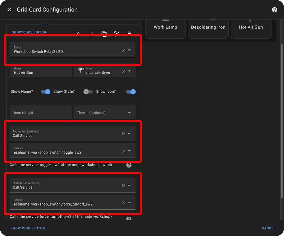
Next, in the “Tap Action” section, select “Call Service” and choose the ESPhome API that we previously added. This will enable toggling the outlet when the button is tapped.
As well as in the “Hold Action” select “Call Service” then select the force turn-off script. This will let you press and hold the button to turn off the outlet without delay.
Once you press the button, the icon will change to amber, indicating that the outlet is now on. When you tap to turn it off, the icon will start blinking, indicating that the outlet is in the process of turning off. And if you prefer to force an immediate turn-off, simply tap and hold the button.
Assembly to the Case
If everything is working as expected, it’s time to proceed with assembling all the components into the 3D print enclosure.
I like to mention that the enclosure shown in the video is the initial version. I made some adjustments to a particular detail that I discovered after printing it. So, the STL file in the link will be slightly different.
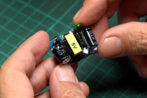
For the DC power supply. I’ve used this compact AC-to-DC converter, it provides a 5-volt output with a capacity of 700 milliamps.
Solder wires to both the input and output terminals. Insert the power supply into the provided block and then attach the cover. Secure the cover in place using an M3 by 15mm screw.
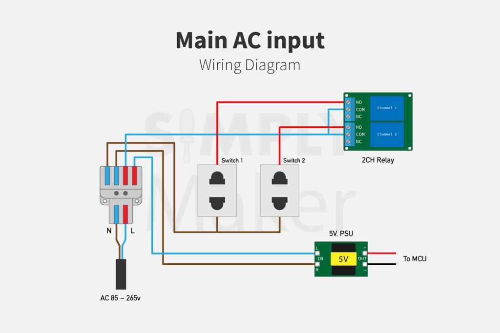
To manage the main input, I use a 2-in 4-out quick-connect terminal block to split the input to both the relay module and a 5-volt power supply. Here is a diagram for the main input.
Moving on to the front cover. Begin by mounting the outlet to the cover using M4 screws. Inserting M4 nuts into the provided slots on the bottom of the cover. The slots are designed to snugly fit. Simply align the nut with the hole and tighten the screw, allowing the nut to securely fit into place.
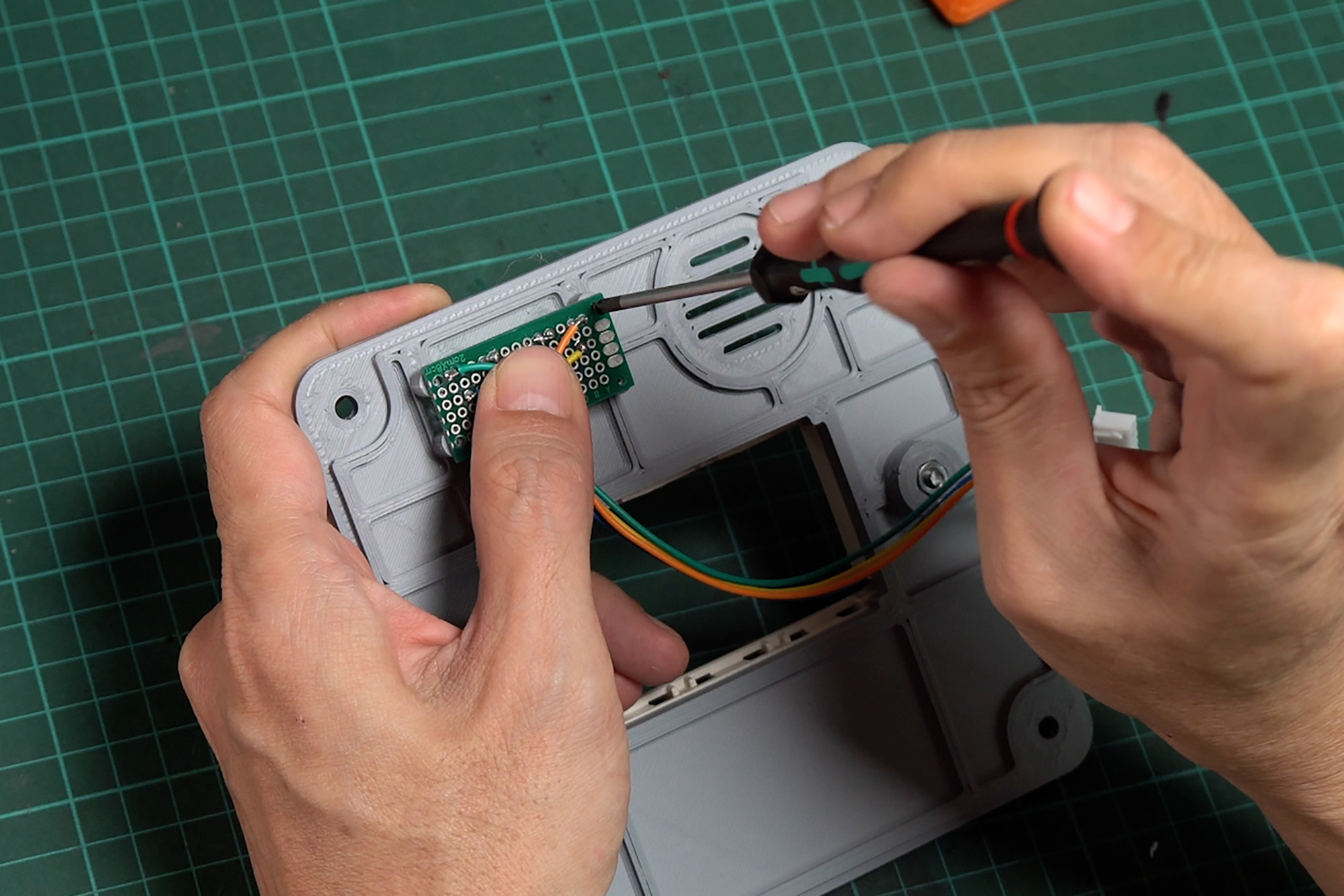
Insert button caps to the cover and mount the front PCB to the front cover with M2 self-tap screws. Make sure that both button caps can move smoothly and without any obstruction when they are pressed.
For the main input wire, I’ll use a 2 by 1 Sq.mm. VCT wire, which has a diameter of approximately 7 mm. On one end, I’ve connected it to a folding AC plug. Connect the other end of the wire to the quick-connect terminal block. Make sure it’s securely fastened.
To keep things in place, use some M3 screws to secure the quick-connect terminal block to the enclosure. Lastly, secure the main wire to the enclosure using a cable clamp.
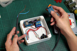
Now we’ve successfully attached all the components. It’s time to attach the cover to the enclosure.
Refer to the provided diagram to properly connect the AC wires. Start by connecting the neutral wire to the quick-connect terminal.
Next, we need to connect both live wires from the outlet to the “Normally Open” terminal on the relay module. Connect a wire from each socket to the corresponding channel of the relay.
Finally, connect the wires from the front PCB to the JST socket on the main PCB. Now we can close the cover. I’ve provided holes for M4 hot melt insert nut.
Outro
The advantage of this DIY outlet is its flexibility and customization. You can tailor it to your specific needs and integrate it seamlessly into your workshop setup with custom function. You’ll enjoy greater efficiency and convenience.
By embedded the control script into the firmware and a physical interface allow the device to operate independently. This means it can perform all essential tasks without relying on Home Assistant or a continuous network connection.
If you have any questions or run into issues, feel free to leave a comment or reach out. Happy making!


