Introduction
In this guide, I’ll walks you through hacking the capacitive touch spring buttons in simple appliances with ESP module using ESPHome firmware. So you can control them wirelessly with Home Assistant.
For many smart home enthusiasts, adding an ESP module opens up new possibilities for creating custom actions, automations, and remote controls. This hack lets you bypass the manufacturer’s limitations, giving you greater flexibility and functionality in your smart home setup.
While the ESP32, ESP32-S2, and ESP32-S3 modules come with built-in touch-sensing GPIOs, allowing them to detect touch inputs directly. However, these GPIOs are designed only for sensing a touch, not for actively triggering one.
In this guide, we’ll focus on how to electronically trigger the capacitive touch buttons on appliances device using GPIO pins and detect touch inputs with ESP modules. Additionally, I’ll outline a potential workaround for ESP modules without built-in touch-sensing capabilities.
What Are Capacitive Touch Springs?
Capacitive touch spring or touch-sensitive spring are a unique type of capacitive touch sensor that uses a compressed spring as the sensing element. Unlike traditional flat capacitive sensors, the spring acts as an electrode that can detect touch from any direction.


It can be found in many appliances like dryers, washers, and microwaves, where touch buttons replace physical ones. It detect slight changes in electrical fields (capacitance) caused by the presence or proximity of a conductive object, such as a human finger.
Capacitive Touch Springs vs. Mechanical Spring Buttons
It’s easy to confuse capacitive touch springs with mechanical spring buttons. Although they look similar, a mechanical spring button operates differently, it activated by direct physical pressure.
When a force is applied to the spring, it’ll compresses, causing the spring wire to make contact and allow current to flow. When the pressure is released, the spring returns to its original position, breaking the circuit and turn the device off.
How to Trigger Capacitive Touch Spring Electronically
In order to simulate pressing a capacitive button you need to altering its capacitance. Unlike mechanical push button, which can be triggered by closing a circuit. I ever successfully use a transistor as an electronic switch connected between the button’s input and output and controlled by the ESP module GPIO.
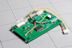
However, triggering a capacitive touch spring button requires a different approach. Since the spring typically has only one pin connected to the board, one way to simulate a touch is by grounding the spring coil to change its capacitance.
During breadboard testing, I can touch a ground wire to its coil to change it capacitance simulated the button pressed, and when I remove the wire the capacitance return to normal simulate the button released.
To accomplish this electronically, I’ll use an optocoupler instead of a transistor, as it provide electrical isolation between the circuits.
What’s Optocoupler?
An optocoupler, also known as an opto-isolator, is a semiconductor device that allows an electrical signal to be transmitted between two isolated circuits. An optocoupler contains an LED and a photosensitive device (often a phototransistor) within the same housing.
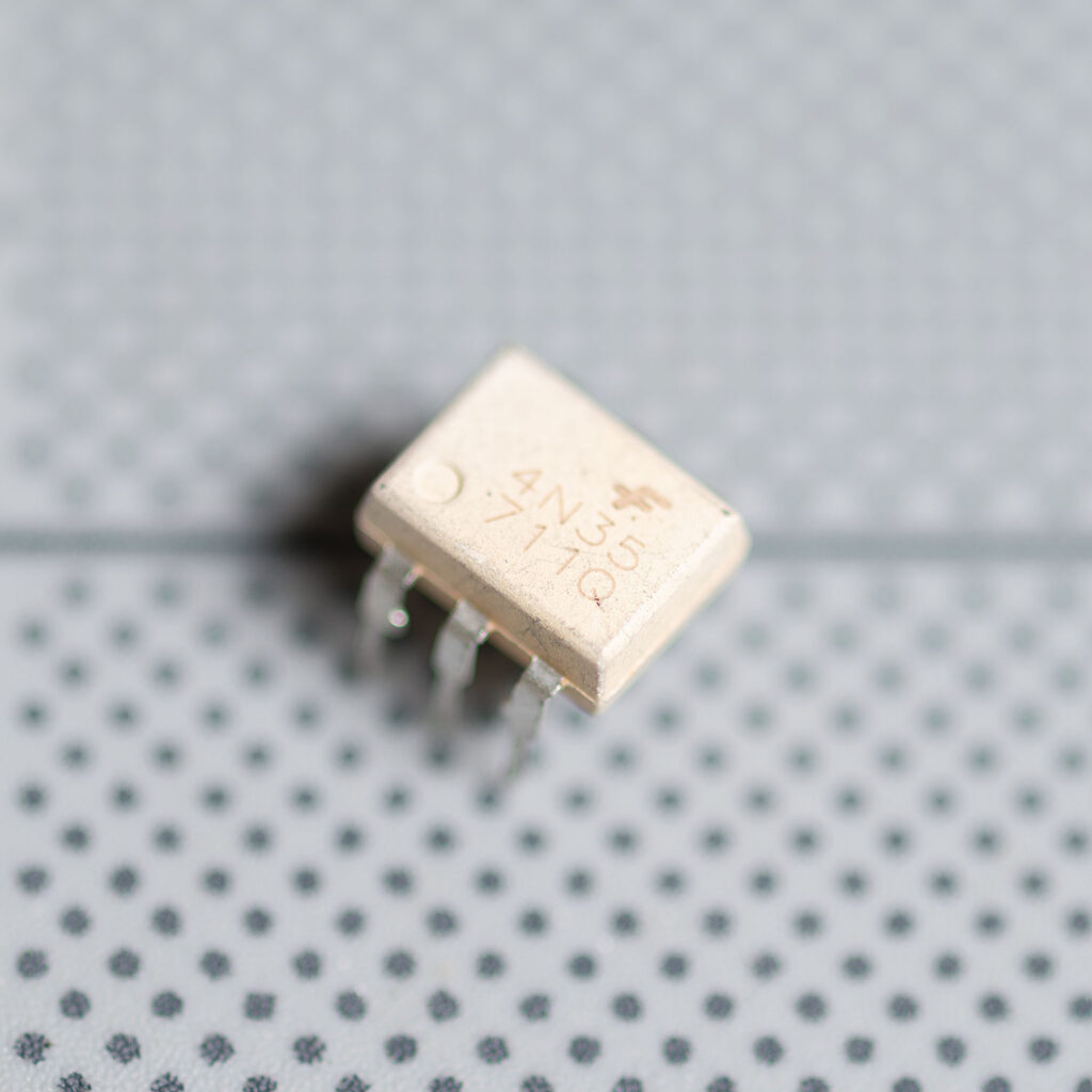
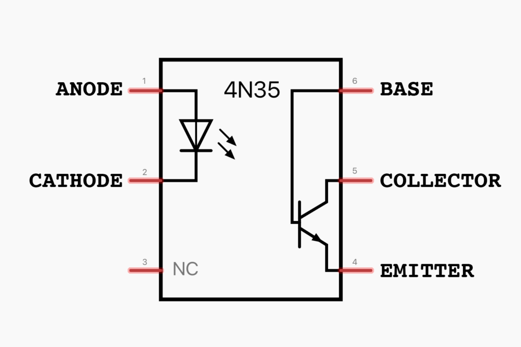
When current applied to the optocoupler, the LED emits infrared light proportional to the current, which can detected by the photosensitive component on the output circuit.
When the light hits the photosensor, a current is conducted and switched on. And when the current flowing through the LED is interrupted, the IR light is cut off, causing the photosensor stops conducting, ending the signal.
How to Connect Optocoupler and Control it with ESPHome
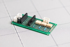
Connect optocoupler to ESP module is straight forward. On the input side, you can connect it to the ESP module much like you would connect an LED. Simply connect a GPIO pin to ANODE and connect ground to the CATHODE.
You also need a resistor to limit the current and prevent burning out the LED. You can calculate the required resistor value using Ohm’s law.
For example, the 4N35 optocoupler which I use in this project, has a forward voltage range between 0.8 – 1.5V with a typical operating current of 10mA. Since the output from the ESP GPIO pin is 3.3V, you’ll need a 180Ω – 220Ω resistor.
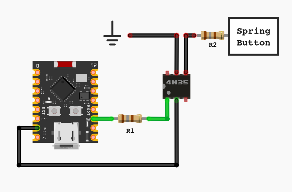
On the output side of this optocoupler is similar to the transistor. It’s has three pins including BASE, COLLECTOR and EMITTER. To connect it, simply attach the ground to the COLLECTOR and a wire from the spring button to EMITTER. The BASE pin which not need in this setup can leave it unconnected.
When working with capacitive touch spring buttons, I discovered that the wire connected to the capacitive button is sensitive to changes in capacitance. Although this wire is typically enclosed within the device, preventing unintentional contact, it may still pick up interference from other electronic components.
To prevent this, you may need to add a resistor between the button and the signal wire to help filter out unintended signals. A 20KΩ resistor or higher usually works well—just ensure the resistor allows the intended signal from the optocoupler to pass through.
Below is example YAML configuration for ESPHome to trigger the optocoupler. I use a Generic Output Button that will activate GPIO Output component with a short pulse (0.2s) to simulate finger touch.
button:
  - platform: output
    name: "Button1"
    output: output1
    duration: 0.2s
output:
  - platform: gpio
    pin: GPIOXX
    id: 'output1'
    inverted: false
When the button is pressed in Home Assistant, the designated GPIO pin pulls high, causing the LED in the optocoupler to emit light. This will triggers the photosensitive component, connecting the output circuit and change the capacitance of the sprint button simulating a finger touch.
Detecting Physical Button Presses
Once the button can be triggered electronically, the next challenge is detecting physical touches on it. While simulating a button press is possible, knowing when the button has been physically pressed is crucial especially when you need to track the actual status of the device to automate some actions.
ESP Module with Touch Pin
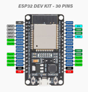
ESPHome provides a built-in ESP32 Touch Pad component which support ESP32, ESP32-S2 and ESP32-S3. By enabling the Touch Pad component in ESPHome’s YAML configuration and using the binary_sensor: component, you can easily detect touch events from touch-sensitive GPIO pins.
Not every GPIO pin on these modules has touch-sensing capabilities. The standard ESP32 includes 10 touch-sensitive GPIOs, while the ESP32-S2 and ESP32-S3 have 14 touch-enabled pins (GPIO1-GPIO14). Be sure to check your board’s pinout diagram and connect the device’s spring button wire to a pin with touch functionality. Since this setup is generally straightforward, I haven’t detailed it further here.
IMPORTANT: If you're using the same signal wire from the spring button to the optocoupler for touch sensing, be careful with the resistor. Adding a resistor to prevent accidental touches, as mentioned earlier, may also block the signal to the GPIO pin, stopping it from detecting touches. You may need to use a lower resistor value or even remove it to allow the signal through.
Here is Example YAML:
#Enabled ESP Touch Pin
esp32_touch:

binary_sensor:
  - platform: esp32_touch
    name: "Touch Pad1"
    pin: GPIXX
    threshold: 1000
    filters:
      - invert:
ESP Module without Touch Pin
Since capacitive touch springs work differently from mechanical push buttons, most microprocessor cannot directly read the trigger signal from a capacitive touch spring since it only slight change of capacitance rather than a simple on/off signal.
Typically it need an additional Touch Key IC to convert this capacitance change into a signal that the microprocessor can interpret. As a workaround, you may use the output from this IC to detect physical touches with standard GPIOs.
To locate the touch IC, capacitive touch springs are usually connect directly to a dedicated touch key IC. You may need to trace the spring button’s connection path to identify the IC.
Once you can identify the touch IC you can refer to its datasheet for corresponding output pin which outputs a readable button press signal. With this pin you can connect ESP’s GPIO to monitor button presses.
Getting output from Touch Key IC
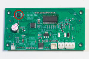
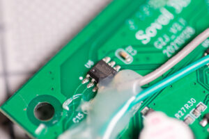
For example, The SOVOL Filament Dryer with capacitive touch spring button. When examining the PCB, I can see the traces from all the buttons run through a capacitor before reaching an IC on the top right. The IC is labeled BS813A-1 which is Touch Key IC.
The traces from the two left-side buttons are clearly visible and connect to Pin1 and Pin2 of the IC. But for the button on the right, the trace goes beneath the IC, making it difficult to visually confirm its connection. In this case, I used a multimeter in continuity mode to verify the connection, confirming that it links to Pin3.
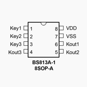
The BS813A-1 (8SOP-A) Touch Key IC datasheet confirms these connections, with Pins 1 to 3 corresponding to Key1, Key2, and Key3. With this information, I can connect the ESP’s GPIO pin to the appropriate Kout pin to monitor each button’s output.
Connecting the IC’s output to an ESP GPIO pin and setting it up as a GPIO Binary Sensor will enable the ESP module to detect the button’s state, even for physical touches. This setup provides reliable status updates essential for accurate automation control.
Here’s an example YAML configuration for ESPHome:
binary_sensor:
  - platform: gpio
    name: "Touch Button1"
    pin:
      number: GPIOXX
      mode:
        input: True
        pullup: True
    filters:
      - invert:
I’ve put together a complete guide on integrating an ESP32 into the SOVOL SH01 Filament Dryer for wireless monitoring and control via Home Assistant, including details on creating a custom PCB. If you’re interested in a more in-depth look at the process, feel free to check out the full guide.
CAUTION: Above method is a workaround, so I cannot guarantee that it will work with your specific device. Its success largely depends on the particular IC and circuit design of your device, and as such, it may not be universally applicable.
Conclusion
With these modifications, you can transform a basic appliance into a smart, customizable device that responds to Home Assistant. By hacking the capacitive touch springs and adding an ESP32, you open up new possibilities for responsive smart home control and custom automations.
In my experience with this method across different projects, it has proven to work quite well. However, there are some limitations to be aware of, especially in real-world implementations where signal interference can be an issue—particularly when dealing with multiple buttons.
I’ve managed to build a reliable system to control a few buttons with only minor, occasional errors, which are generally manageable. The primary challenge appears to come from using prototype PCB boards, which make it difficult to effectively isolate sensing wires.
A custom PCB with well-spaced signal traces could help minimize these issues, making the build process easier and more reliable. I plan to develop a custom PCB design in the future, so stay tuned!
Disclaimer: This blog post is intended to share ideas and inspire DIY projects. While we’ve taken care to provide accurate information, we are not responsible for any losses, damage, or injuries that may result from following the instructions or using the content. Please proceed with caution and follow safety guidelines when working on your projects.


