Introduction
Today, I’ll guide you through the process of wirelessly flashing Tuya IOT devices with ESPHome firmware using Tuya Cloudcutter.
Additionally, I’ll show you how to use Itchiptool to extract pin configuration for the ESPHome YAML, enabling integration with Home Assistant for local control.
Furthermore, I’ve added a custom ESPHome YAML tailored to control the device behaviour to meet specific needs.
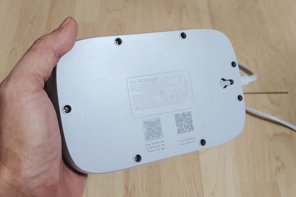
In this guide, I’ll be using the LDNIO power strip to demonstrate the process. This power strip is equipped with a Tuya CB2S module that uses the Beken BK7231N chipset, which is compatible with Tuya Cloudcutter.
About LDNIO Power Strip

I picked this LDNIO Wifi Power Strip due to its sleek design. It’s notably more compact than other smart power strips and a rounded corners for a stylish modern look.
The power strip features 4 output channels (3 AC outlets and a 4 ports USB charger). Each outlet can be controlled individually through software.
The USB charger module includes 3 USB-A ports, one of which supports QC3.0, alongside a 30W USB PD port.
Safety was a top priority when selecting a power strip, LDNIO is a trusted brand of expertise in power outlets, chargers and cables.
The outer case of the LDNIO power strip is constructed from high-quality, fire-resistant PC shell material, ensuring durability and safety.
Compared to other power sockets, the LDNIO power strip features a thicker construction and feature load of safety protections.
LDNIO Smart Wifi Power Strip: Aliexpress | Shopee Thailand

Feature Specifications:
- Rated Parameter: 2500W 10A 250V
- Number of AC Outlets: 3 (International, EU, UK Socket Options)
- Number of USB Ports: 3 (QC3.0) + 1 PD (30W)
- PD Output: 5V=3A, 9V=3A, 12V=2.5A, 15V=1A, 20V=1.5A 30W(Max.)
- QC Output: 5V=3A, 9V=2A, 12V=1.5A 18W(Max.)
- Wireless Connectivity: WiFi
- Cord Length: 2M. (US, EU, UK Plug Available)
- Compatibility: Tuya Smart, Smart Life apps
- Safety Features: Overheat detection, Surge protection, Overload protection
Flashing Process
Prerequisite
If you haven’t installed Tuya Cloudcutter yet, I have a comprehensive step-by-step guide to help you set it up on an affordable Raspberry Pi Zero 2W. Be sure to check it out before proceeding.
During the flashing process, you will need to power cycle your device several times. It’s much more convenient to use an outlet with a switch to power your device.
Identifying Your Device’s Firmware Version
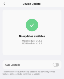
Even though Tuya Cloudcutter provides an extensive list of device profile database you can select from, finding an exact match can be challenging, especially for unbranded devices.
Additionally, some manufacturers may change the chip inside a device while retaining the same outer shell and model name. I’ve found it easier to match the device by its firmware version.
To check your device’s firmware version, follow these steps:
- Add the Device to the Smart Life App: Open the Smart Life app and add your device as you normally would.
- Enter the Device Page: After successfully adding the device, navigate to its page within the app.
- Edit Device Settings: Click on the edit device icon (pencil icon) located in the top right corner.
- Check for Device Updates: Scroll down to the bottom of the page and click on “Device Update.”
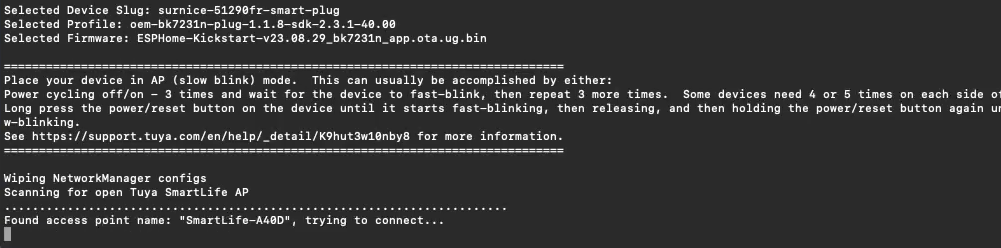
Run Tuya Cloudcutter and flash ESPHome Kickstart
Start by logging into your Raspberry Pi via SSH. Use Terminal for macOS/Linux or PuTTY for Windows. Replace piusb.local
ssh pi@piusb.localNavigate to the Tuya Cloudcutter directory and run the script.
cd tuya-cloudcutter
sudo ./tuya-cloudcutter.sh -r
Wait for the Docker image to build. Once completed, select the Flash 3rd Party Firmware2
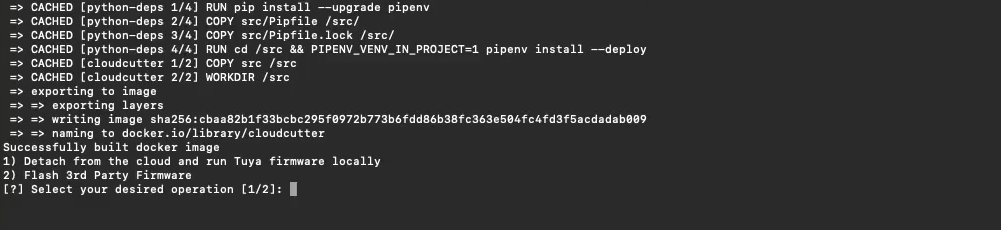
Next, you will be prompted to choose your device. As mentioned earlier, I prefer to match the device with firmware, so I will select By firmware version and name

Now select the firmware version. For the LDNIO Power Strip, the firmware version is 1.1.8. There may be multiple entries for each firmware version, so you will need to choose the one that closely matches your device type.
Sometimes, this process involves a bit of trial and error. If your initial choice doesn’t work, you may need to repeat the process and select other device names with the same firmware version.
To stop script and repeat the process press
.Control + C
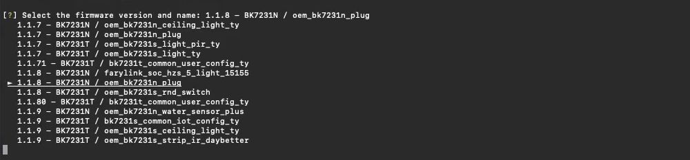
Scroll down until you find your firmware version. There are three 1.1.8 firmware in the list, I can discard the BK7231T, so I select 1.1.8 - BK7231N / oem_bk7231n_plug
Wait until the safety check is complete, then select ESPHome-Kickstart firmware.

To flash the firmware, your device needs to be in Access Point (AP) mode. The process may vary on different devices.
The process is similar to putting the device in pairing mode used for adding devices to the Tuya app. If you are unsure how to do this, refer to your device’s documentation.
For the LDNIO power strip:
- Press and hold the device button for 5-8 seconds, then release. The LED will blink rapidly, indicating pairing mode.
- If the device was previously added to the app, it will now be removed.
- Press and hold the button again, after release the LED blinks slowly, indicating AP mode.
In the terminal, you should see a message like: Found access point name: "SmartLife-XXXX", try to connect
Wait for the process to complete. The terminal will prompt you to power cycle the device and put it in AP mode again.
Disconnect the power strip from the outlet. After the LED go off, wait for few second and reconnect the power and put it back into AP mode following the steps above.
If everything works as expected, Tuya Cloudcutter will start flashing your device and show its progress in the terminal.
Once the flashing is complete, Tuya Cloudcutter will close and return you to the command prompt.
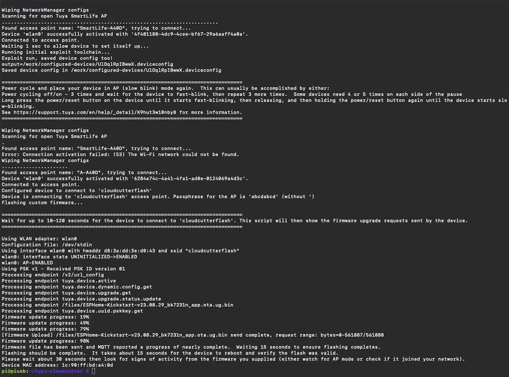
With the ESPHome Kickstart firmware successfully flashed onto your device. You can safely power down the Raspberry Pi and close the terminal.
Before proceeding further, I recommend power cycling your device once more to ensure smooth operation.

Setup ESPHome Kickstart to access your local area network
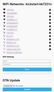
To begin, use wifi to locate and connect to the access point broadcasted by your newly flashed device. The access point name will typically start with “kickstart-“.
Once connected, it should automatically redirect you to the Wi-Fi settings page. If not, you can manually enter 192.168.4.1 in your browser’s address bar.
Next, select your local access point name from the list and enter the corresponding password.
Click Save to confirm your settings. Be sure to power cycle your device once more to apply the changes.
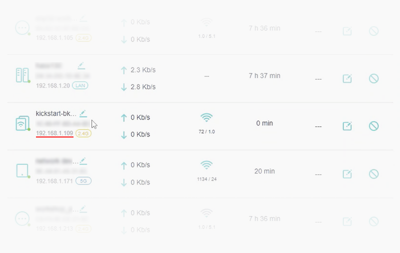
Your device should now be connected to your local area network. To confirm this you can use a mobile app like Fing or your router’s administration page to scan for devices on your network.
Make note of its IP address you will need it for the next step.
Generate ESPHome YAML Configuration
To simplify the process of obtaining your device configuration and GPIO pin layout, you can use a tool called Itchiptool (available for Windows only), developed by Libretiny, the same team behind ESPHome and Tuya Cloudcutter.
You can download Itchiptool from: https://github.com/libretiny-eu/ltchiptool/releases
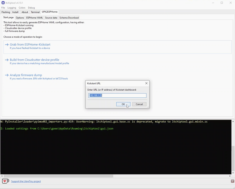
Once you have opened the Itchiptool, navigate to the UPK2ESPHome tab. Click Grab from ESPHome-Kickstart and enter the IP address of your device, which you obtained in an earlier step.
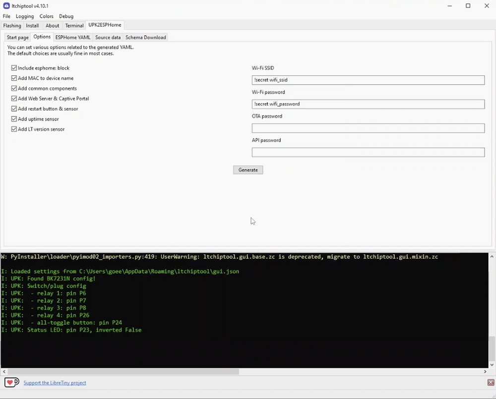
After Itchiptool finishes reading your device, it will switch to Options page.
From here, you can select options to include in the YAML file. In the example, I have included all the options, this can be easily removed later if needed.
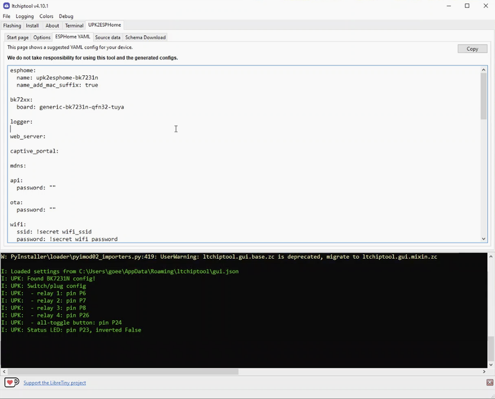
Once everything is set, click Generate. This will provide you with a suggested YAML configuration that includes all the GPIO pins for the relay, button, LED, etc.
You can then copy and paste this configuration into ESPHome.
If your device already have device profile you can pull YAML configuration form UPK2ESPHome website.
Integrate to Home Assistant
Add New Device to ESPHome
Now it’s time to integrate the power strip into Home Assistant. First, you have to add the new device to ESPHome Add-on.
- Open Home Assistant and navigate to the ESPHome dashboard.
- Click NEW DEVICE to create a new device configuration.
- In “Create configuration”, give your device a name
- In device type select BK72xx (for LDNIO Power Strip)
- Next, choose CB2S Wi-Fi Module from BK72xx board list (for LDNIO Power Strip)
- Finally, you will prompted to install, click SKIP.
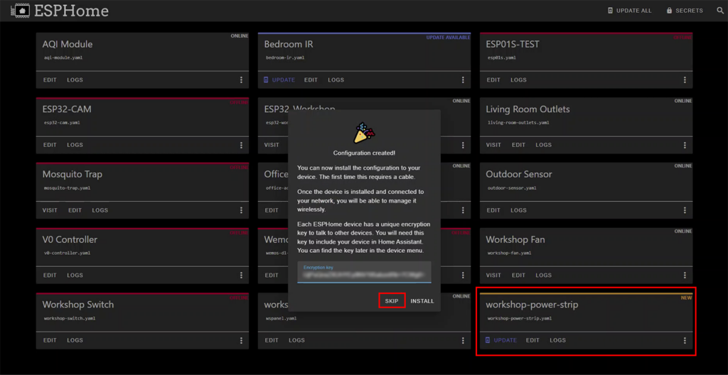
Your new device should now be added to the ESPHome dashboard. Click EDIT your newly added device to edit its YAML configuration.
Edit Device’s YAML Configuration
Now you can paste a configuration from Itchiptool to your new ESPHome device.
However, I personally like to copy just part about sensor and button below wifi:esphome:
Make any necessary changes to match your system preferences. You can also choose to update configurations wirelessly later. Once you’ve finished editing the file, click SAVE and then INSTALL.
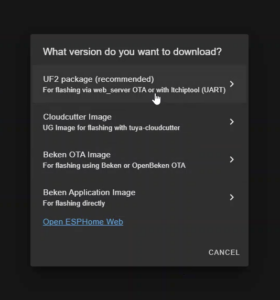
For the install method, select Manual Download.
Wait until compiling to finished, then download the generated firmware as UF2 package.

Update ESPHome Kickstart Firmware
Next, open your browser and connect to your device’s settings page using the same IP address you enter in Itchiptool.
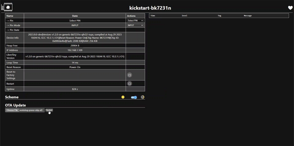
Click Choose File under OTA Update and browse to your downloaded UF2 firmware file. Then click Update.
Once the update is complete, your new device should discovered in Home Assistant, if not you can add it manually in Devices & Services.
Now you can test each power strip function by pressing its physical button and trying to control it from the dashboard.
Note: In my system, whenever I added a new BK72xx device, it kept re-discovering in Home Assistant even after I had already added it.
I found that I could safely ignore it and reboot the Home Assistant host, after which the problem would disappear. I’m not sure if this is a common occurrence or specific to my system.
Customise Power Socket Configuration
The default configuration is working as expected. You can press the button on the power strip to toggle all sockets.
Each socket can be controlled individually via Home Assistant Dashboard. But there are a few things I like to improve.
Modify Status LED
The default status LED will blink red and white while the device is not connected to the Home Assistant server and stays red after it connects.
However, it doesn’t indicate the status of the outlets, whether they are turned On or Off. This is because the LED GPIO pin is assigned to a Status Led component which cannot be controlled.
To reflect the outlet status with the LED light, I will use Status LED Light component instead of status_led. I chose not to use the output component because I want to retain the status_led behavior for showing connection status.
Replace the status_led:
light:
  - platform: status_led
    name: "Button Led"
    id: button_led
    pin:
      number: P23
      inverted: false
    on_turn_on:
    - binary_sensor.template.publish:
        id: led_status
        state: ON
    on_turn_off:
    - binary_sensor.template.publish:
        id: led_status
        state: OFF
    internal: True
You can control LED color (Red or White) by set
pin: inverted:toTrueorFalse
I’m set the status LED light to internal: True
To expose the state of status light in Home Assistant, I use binary_sensor instead. By adding template binary sensor within binary_sensor:
binary_sensor:
    ...
  - platform: template
    name: LED Status
    id: led_status
Modify Physical Button Behavior
In the YAML configuration generated by Itchiptool, the momentary button on the power strip is assigned to a GPIO binary sensor component, which controls all relays using a switch.toggle
This setup means that pressing the physical button toggles the state of all relays simultaneously.
However, this configuration presents a problem. If any of the relays are in a different state (turned ON or OFF individually through Home Assistant), pressing the physical button will toggle all relays, leading to mixed states.
Instead of turning all sockets ON or OFF simultaneously, some will turn ON while others turn OFF, which is not the desired behaviour.
This problem is easily fixed by adding template switch. Additionally, I need further control over the status LED to ensure it only turns off when all relays are OFF. If any relay is ON, the LED should turn on to indicate its status.
This requires an additional script to monitor the state of each relay and control the status LED accordingly.
With these changes, pressing the button on the power strip will still toggle all the relays ON or OFF. However, if any relay is ON, pressing the button will turn all the relays OFF.
You can also turn all relays ON while some switches are already ON by pressing and holding the button for at least 3 seconds before releasing it.
First, add the following script to your YAML.
script:
  - id: condition_toggle_script
    mode: restart
    then:
      - if:
          condition:
            or:
              - switch.is_on: switch_1
              - switch.is_on: switch_2
              - switch.is_on: switch_3
              - switch.is_on: switch_4
          then:
            - switch.turn_off: switch_1
            - switch.turn_off: switch_2
            - switch.turn_off: switch_3
            - switch.turn_off: switch_4
            - light.turn_off: button_led
          else:
            - switch.turn_on: switch_1
            - switch.turn_on: switch_2
            - switch.turn_on: switch_3
            - switch.turn_on: switch_4
            - light.turn_on: button_led

  - id: switch_turn_on
    then:
      - if:
          condition:
            - not:
                script.is_running: condition_toggle_script
            - or:
                - switch.is_on: switch_1
                - switch.is_on: switch_2
                - switch.is_on: switch_3
                - switch.is_on: switch_4
          then:
              light.turn_on: button_led

  - id: switch_turn_off
    then:
      - if:
          condition:
            - not:
                script.is_running: condition_toggle_script
            - switch.is_off: switch_1
            - switch.is_off: switch_2
            - switch.is_off: switch_3
            - switch.is_off: switch_4
          then:
            light.turn_off: button_led
Add on_turn_onon_turn_off
switch:
#Relay 1 example
- platform: gpio
  id: switch_1
  name: Relay 1
  pin: P6
  on_turn_on:
    - script.execute: switch_turn_on
  on_turn_off:
    - script.execute: switch_turn_off
Modify binary_switch_all
binary_sensor:
  - platform: gpio
    id: binary_switch_all
    pin:
      number: P24
      inverted: true
      mode: INPUT_PULLUP
    on_click:
      - min_length: 50ms
        max_length: 350ms
        then:
          - script.execute: condition_toggle_script
      - min_length: 3s
        max_length: 8s
        then:
         - switch.turn_on: switch_1
         - switch.turn_on: switch_2
         - switch.turn_on: switch_3
         - switch.turn_on: switch_4
         - light.turn_on: button_led
    internal: True
Alternatively, you can change the hold action to toggle USB outlet (switch_4).
    on_click:
      - min_length: 50ms
        max_length: 350ms
        then:
          - script.execute: condition_toggle_script
      - min_length: 3s
        max_length: 8s
        then:
         - switch.toggle: switch_4
         - light.turn_on: button_led
Finally, add a global template button to button:
button:
    ...
  - platform: template
    name: "Global Switch"
    id: switch_all
    on_press:
      - script.execute: condition_toggle_script
Optional Configuration
To enhance your setup, consider adding a web server. This allows you to easily access the device’s configuration and status via a web interface. Add the following lines to your YAML configuration:
web_server:
  port: 80
  local: true
Additionally, assigning a fixed IP address to your device can make it easier to access its web server. To do this, add the following code to the wifi:
wifi:
  ...
  manual_ip:
    static_ip: 192.168.1.55
    gateway: 192.168.1.1
    subnet: 255.255.255.0
So with just a few YAML modifications, you can now personalise your LDNIO power strip to better suit your specific needs.
For your convenience, I’ve included the YAML file that I’ve used as a reference. Feel free to explore and modify it to match your requirements.
LDNIO Power Strip YAML: ldnio-power-strip.yaml
Conclusion
Tuya Cloudcutter serves as more than a tool for detaching Tuya-based IoT devices from provider cloud to local use. It’s also a gateway to greater customization and control of your device.
With ESPHome, you can tailor your devices to precisely fit your needs, whether it’s fine-tuning behaviour, integrating additional features, or enhancing security and privacy.
With Tuya Cloudcutter and ESPHome you’re not just limited to the functionality provided out of the box; instead, you have the freedom to shape your smart home experience according to your preferences and requirements.
So, dive in, play around, and make your devices work just the way you want them to.
Finally, please note that not all Tuya devices can be flashed using Tuya Cloudcutter. Only those equipped with a supported chip can undergo this process.
Additionally, sometimes manufacturers just switch to a different chip inside their product while maintaining the same shell and model name. Therefore, a device that was once worked may not necessarily support it in future batches or reorders.
Relate Link
- Home Assistant: Home Assistant home page.
- ESPHome: a system to control your microcontrollers by simple yet powerful configuration files and control them remotely through Home Automation systems.
- Tuya Cloudcutter: A tool that disconnects Tuya IoT devices from the cloud, allowing them to run completely locally.
- Itchiptool: Universal, easy-to-use GUI flashing/dumping tool for BK7231, RTL8710B and RTL8720C.
- LDNIO Official Store: Link to LDNIO Official Store on Aliexpress.


Hi friend,
I apreciate the detailed tutorial.
I’m trying to install it on a power strip I bought from Ali, but I cannot even install the kickstarter.
I’ve tried tons of profiles from the list, but l always get that the profile I choose did not work for my device.
I tried on 3 devices. None I got success:
1) Power Strip Wifi (AVATTO): 4 gags + USB. The firmware it uses is 1.1.17 (other modules 1.0.4)
2) Power Strip Wifi (local seller): 4 gangs + USB. FW 1.1.8 (other modules 1.1.8)
3) DImmer Tuya Wifi (not RGB, just DC): FW 2.0.21 (other modules 2.0.21)
I dont have Raspbery, so I made a fresh pendrive with ubuntu and configured cloudcutter on it. It says my wifi is compatible.
I don’t know what else I can do. I dont want to get soldering direct to chip.
Thanks anyway.
Thanks for your comment.
Unfortunately, I don’t have experience with using a USB pendrive setup, so I can’t provide specific advice on that method.
The best next step would be to search for your specific device models online to see if others have had success flashing them. And if you’re able to safely open the device, identifying the exact MCU inside can help narrow down the right profile and increase your chances of success—without having to solder directly.
Good luck, and thanks again for checking out the tutorial!