Introduction
The DIY portable mobile soldering station and power supply using a Makita 18-volt battery. I’ve made this for a couple of years and use it regularly. It serves me very well without any problem. The performance is quite impressive. With a fully charged battery, It can heat up to 320 degrees within 30 seconds.
This soldering station uses a clone Hakko T12 controller, which is extremely good for the price. The soldering iron handle is fully compatible with T12 series soldering tips. The T12 soldering iron has a large collection of tips you can choose to match your application.
Helpful link for T12 soldering tip selection: https://tinyurl.com/hakko-t12
The step-down power supply is a 1.2-32 volt 5 amp 75 watt with LCD display that can show real-time voltage and current. It also has an input voltage reading option to check the battery status.

Material List

3D PRINT PARTS
- Printables.com: Makita T12 Soldering Station Enclosure
- Thingiverse.com: Makita T12 Soldering Station Enclosure
- Thingiverse.com: Makita Battery Mount
ELECTRONIC COMPONENTS FOR THIS PROJECT
- DIY T12 Soldering Station Kits: Aliexpress | Shopee Thailand
- 5A Step-Down Power Supply: Aliexpress | Shopee Thailand
- Makita Battery Terminal (644808-8): Aliexpress | Shopee Thailand
- KCD1-101 Rocker Switch (X2): Aliexpress | Shopee Thailand
- Makita Compatible Terminal (Alternative): Aliexpress | Shopee Thailand
- Extra T12 Soldering iron Tips (Optional): Aliexpress | Shopee Thailand
TOOLS, SUPPLY, AND FASTENING
- Wire Crimping Tool: Aliexpress | Shopee Thailand
- Spade Connector: Aliexpress | Shopee Thailand
- JST-XH 2.54 3P Male Connector: Aliexpress | Shopee Thailand
- 18 AWG wires (Red and Black):
- M6 x 10mm Socket Head Screws (X4):
- M3 x 5mm Button Head Screws (X4):
- M2.5 x 5mm Flat Head Screws (X4):
- M2 x 5mm Flat Head Screws (X4):
FILAMENT USE IN THIS PROJECT
- eSun PLA+: Aliexpress | Shopee Thailand
- eSun ePLA-Matt: Aliexpress | Shopee Thailand
How to Make
SUBSCRIBE TO THE CHANNEL: http://shorturl.at/gikA4
The soldering station consisted of 2 main parts. The battery mount and the enclosure. The enclosure is modified from a 14-volt system, designed by stratosvasilas on Thingiverse.
It’s included 3 print parts. The main box and 2 mounting plates. The top one is for the step-down power supply and the other one is for the T12 control board.

First, let’s start with the battery mount.

Battery Mount
The battery mount is originally designed by bitsplusatoms on Thingiverse. I modified it to fit with Makita’s terminal block that I currently have (MAKITA TERMINAL Part No. 644808-8).
If your battery doesn’t have an extra small pin on the side. You may use an original battery.

The battery mount is split into two parts with a terminal block sitting in between. The print parts have a grove, to hold the terminal block firmly in place. We need to apply some glue to hold them together. Use acrylic glue or AB epoxy for strong bonding.
Apply a thin layer of glue to the part’s contact surface. Insert the battery terminal into the slot. And attached the parts together. Use quick clamps to clamp it together and Let the glue dry.

The Enclosure
Let’s continue with the enclosure. Start with the power supply plate.
Power Supply Plate
The PSU I use is a 5A 75-watt step-down module. The main role of the PSU is to control the output voltage to the banana connectors when you use it as a mobile power supply. The output from PSU will be limited by the voltage delivered by the battery.
The T12 controller board itself requires input ranging from 12 to 24-volt. So voltage setting is not quite necessary when using it with a soldering iron. Just make sure that the output is over 12v, the lower voltage will affect the heating time. The maximum output from my fully charged battery is around 20-volt and gradually decreases while using.
First, we need to remove the input and output blue screw terminals.
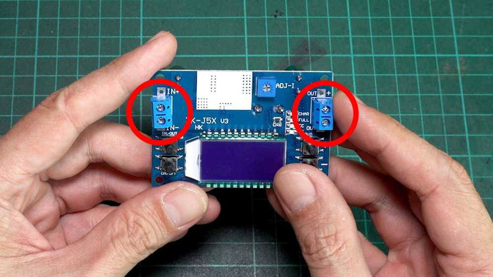
Use the desoldering tool or desoldering wick to remove excessive solder. Then use the punching tool or awl to push the connector out while applying some heat.
Next, we need to solder the wires to the board as shown in the diagram below.

For input, I use red and black 18-AWG wire. Crimp one end with a female spade connector. Then solder the other end to the board’s input pads. The red wire spade connector will connect to the first switch [wire (2)]. The black wire will go to the battery [wire (1)].

For the output, We need to connect the output to the banana connectors and also to the T12 controller board [wire (2-3) and (3-4)]. The positive will pass through the second switch.
Use 2 wires, and twist them together. Solder the twisted end to the banana ring terminal connectors. Then Cover the contacts with a heat shrink tube.

For the black wires [wire (2-3)], crimp one end with a JST-XH connector. This one will go to the T12 controller board. Solder the other end to board output negative (OUT-).
For the red wires [wire (3-4)], crimp one end with a female spade connector. This one will go to the second switch. Solder the other end to board output positive (OUT+)

Next, attach the heatsink to the power supply board using the supplied double-sided tape. Stick it firmly on the area marked with a white silkscreen box.
Insert the blue button cover caps, which are supplied with the power supply kit, into the provided holes on the top plate. Assembly the PSU to the top plate. Carefully align all 4 buttons into the button cap hole. Make sure that all the buttons can press down and spring up freely. Use button heads M3x5 screws to secure the power supply board to the plate.
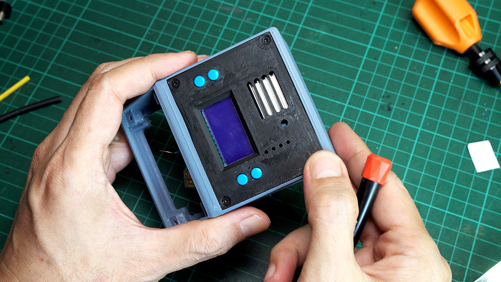
Assemble the power supply, banana connectors, and switches to the enclosure case. Secure the PSU plate with four M2x5 flat-head screws.
Connect the wire according to the diagram.
Input:
Connect the red wire with the spade connector [wire (2)] from the input to the first switch. Use additional red wire with the spade connector on both sides [wire (1)]. Connected one end to the first switch (main switch) and the other end will go to the battery’s positive pin.
Output:
Assemble the banana connectors to the enclosure. Connect the ring terminal from the output to the connectors according to its color. Connect the red wire spade connector, from the output to the second switch [wire (3-4)].
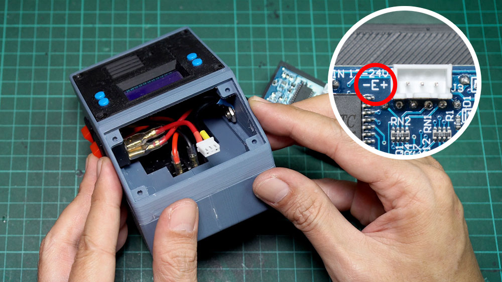
Attach the enclosure to the battery mount base using four socket head M6x10 screws. You can choose the way you insert the battery (from front or back) by rotating the battery mount direction. It totally depended on your personal preference.

Connect input wires to the battery terminal. Please make sure that the red wire, from the first switch, connects to the battery connector pin marked with a + sign and the black input wire connects to the pin marked with a – sign.
T12 Soldering Iron Controller Plate
For the soldering iron, I use a T12 soldering iron kit from Aliexpress. The kit included all the parts you need for about 12 dollars. The kit includes a controller board, Handle, 1 iron tip, aviator plug, all the wiring, and even some spare parts.

To assemble the controller board, start with the LED. Insert the LED’s pin into the PCB. Please make sure that the long pin goes to the pad mark with a + sign. Use small soldering iron tips. And carefully weld the LED pins to the board. Make sure that the tip does not touch other electronic components around.

Assembly the female aviator plug with the front plate. The aviator plug has a tongue for aligning the pins together while connecting. Make sure that the tongue is aligned to the top side. Insert a washer into the place and screw in the aviator plug’s nut.

Attach the controller to the front plate. Insert the rotator knob into the provided hole and align the aviator plug’s pins into the PCB pads. Make sure that all pins are fitted perfectly. Push the PCB to the plate until the rotator base touches the front plate. Insert a washer into the rotator and screw in the rotator’s nut.

Check that the PCB and the front plate are parallel. If everything is in place use a wrench to tighten both nuts. Use a small soldering iron tip to weld all the aviator plug’s pins to the controller board.
Crimp another red wire [wire (5)]. On one end crimp it with a spade connector. And on another end, crimp it with a JST-XH connector. Connect the spade connector to the second switch.
On another end, insert it into the 3-pin JST-XH male connector housing. Make sure that it goes to the “+” pin on the controller board. Insert the other crimped black wire [wire (2-3)], from the output to the housing slot that goes to the board “-” pin. The pin on the center is for the AC ground wire. In our setup, it will be left blank. Please recheck the marking on your board for the wire orientation. The pin orientation may vary depending on the controller board version.
Connect the JST connector to the controller board. Then attach the front plate to the enclosure with M2.5×5 flat-head screws. Now, our enclosure is finished and ready to test.
Soldering Iron Handle
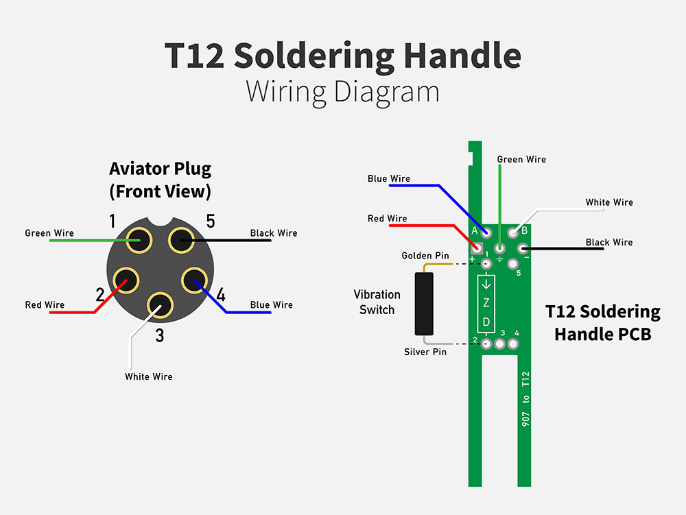
Start with assembling the handle by welding the vibration switch to the PCB.
Make sure that the switch’s pins go to the correct pad hole. The vibration switch pins are marked with gold and silver. Then connect all the wires according to the diagram.
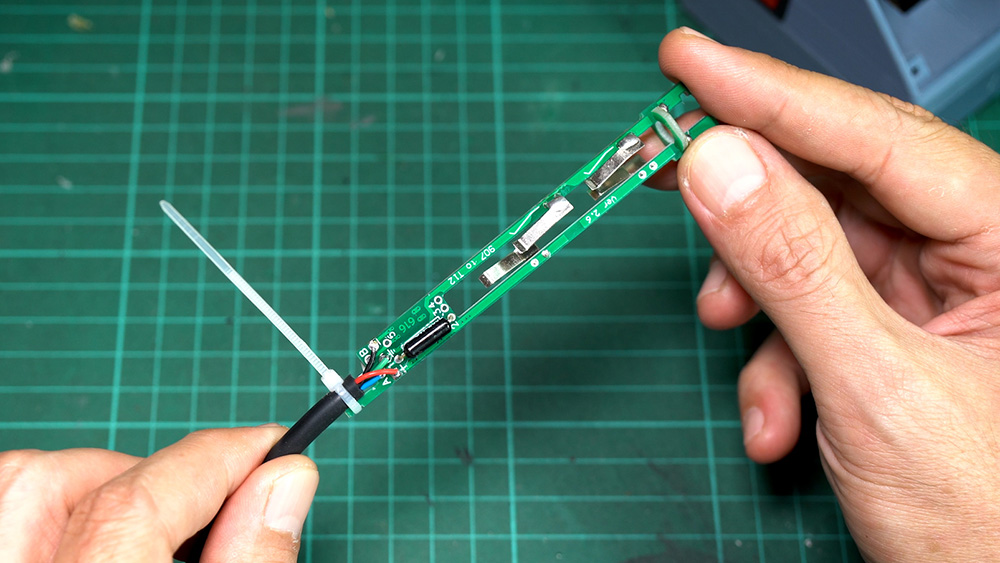
Insert the PCB into the handle. Align the PCB into the groove inside the handle. Slide the PCB into the handle until it sits in place. Then screw in and tighten the handle cap.
Next, we need to solder the cable to the aviator connector. To do this we need to remove the shell from the connector.

Insert the cable into the shell and solder each wire to the connector pin. Each pin will have a small number embossed on the front of the connector. This indicates the pin’s number. Follow the diagram and carefully solder each wire to the pin. Take your time, and double-check the pin number before connecting. After finishing, assemble the shell to the connector.

Using the Soldering Station

The first switch. This is the main switch to control the power from the battery to the power supply unit.
The second switch is for the Soldering iron. If the default boot of the power supply is set to off. You have to press the lower left button (Power Button) to turn on the board output.
The red led light blinking means the soldering iron is heating up and will stay on when it reaches a set temperature. The screen will show the current temperature in Celsius. To adjust the temperature, just rotate the rotator knob.
PSU Default Boot
To set the default boot of the power supply. Long press the lower left button and release. The screen will show the new default boot setting.
If set to ON, the output will turn on automatically when the PSU gets the power.
If set to OFF, The output will turn off when the PSU gets the power. You have to press the power button to turn the output on.

Vibration Switch Setting
This T12 handle has a vibration switch to wake the controller from sleep or shutdown state and heat up to the set temperature when you pick up the handle. There are some settings needed for this function to work properly.

To enter the setting menu, long press and release the rotator knob. The screen will show P00 and after 1.5 seconds it will show its current setting. Rotate the knob to change the setting. Short press to save and switch to the next menu. The following menus are essential for the vibration switch.
Menu P05: This is Sleep time in minutes. When in a sleep state, the soldering iron will decrease its temperature to 200 degrees. To save battery, I set it to
Menu P06: This is Shutdown time. When shutdown 000 will display on the screen and the soldering iron will stop heating. I set it to 4.
Menu P08: This is Wake mode. Set it to 0, to enable the vibration switch. You can also rotate the rotator knob to wake up the controller.
All other menus are mostly for calibrating and fine-tuning the controller. It’s a good idea to leave it to factory default.
Other Resources
Hakko T12 Controller Menu Setting Document:
https://drive.google.com/file/d/1-d3cM3xsYJkP1jmw6Jt1GJuqiGjJvqe0/view?usp=sharing
Helpful link for soldering tip selection:
https://www.hakko.com/english/products/hakko_fm2027_2028_tips.html#t12
The original soldering station is designed by stratosvasilas:
https://www.thingiverse.com/thing:4232983
The original battery mount is designed by bitsplusatoms:
https://www.thingiverse.com/thing:3875426
SUBSCRIBE TO THE CHANNEL: http://shorturl.at/gikA4
DISCLAIMER: This aricle, video and description may contain affiliate links that support our channel. We are not responsible for any losses, damage, or injury in connection with the use of our content.


I realize this has been around for a while but is there any chance you have a Dewalt version of this? I have all Dewalt tools and would like to make one of these that fits what I have.
I totally get it. I try to stick to one tool system as well.
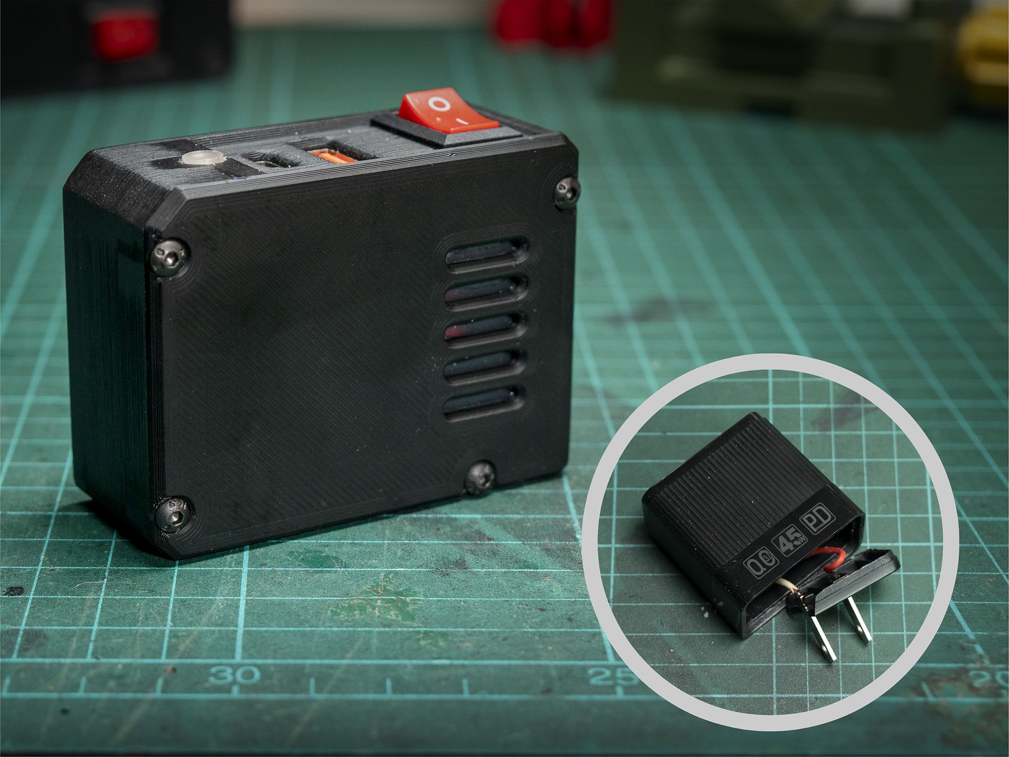
Unfortunately, I don’t have a Dewalt tool to test with. However, this adapter might work, but you’ll need to modify it to fit the top module.
Your projects are awesome and appreciate all your hard work putting them together. Did you happen to make your pcb vise as seen in this build or did you purchase that? I’ve been looking to make a very simple one.
Thanks! I really appreciate your support. 😊
I made the PCB vise a while ago, but I can’t remember if I remixed it or designed it from scratch. Anyway, I found it a bit too bulky, and the structure was too thin—it started bending over time. So I switched to this one instead: https://simplymaker.net/3d-printing/3d-printed-upgrade-for-relife-rl-601l-fixture-enhanced-for-soldering-tasks/.
It’s much more sturdy and works great for soldering tasks!