Introduction
My old work light has stopped working after serving me well for over a decade. So I’ve been looking for a replacement.
First, I want something that is brighter than my old work light. And I like a swing arm that allows me to adjust the light angle easily.
Secondly, It must be mounted on the table to save space on my small workbench.
I also prefer some kind of wireless control, so I don’t have to keep reaching for the switch.
Since I’ll be using this as a work light, I think it’ll be more convenient for me to use an analogue switch instead of having to use my smartphone app all the time. So the dedicated RF remote control seems to be the best solution.
Unfortunately, I couldn’t find one that fit all my requirements, so I decided to build my own.
Material List
3D PRINT PARTS
- Printables.com: Super Bright Swing Arm table mount LED
- Thingiverse.com: Swingarm LED Desk Lamp
COMPONENTS FOR THIS PROJECT
- AC Led Flood Light 100W: Aliexpress | Shopee Thailand
- Tablet holder swing arm: Aliexpress | Shopee Thailand
- Wifi + RF 433MHz Tuya Smart Light Switch: Aliexpress | Shopee Thailand
- 2mm White Transparent Acrylic Sheet: Aliexpress | Shopee Thailand
- Drawer Handle: Aliexpress | Shopee Thailand
ELECTRONIC SUPPLY AND FASTENING
- Brass Hot Melt Inset Nuts SL-type (M3xD5xL4) – x4: Aliexpress
- Brass Hot Melt Inset Nuts SL-type (M4xD6xL5) – x1: Aliexpress
- Button Head M5 Screw – 30mm :
- Hex Head M4 Screw – 15mm :
- Socket Head M3 Screw – 15mm :
- Flat Head M3 Screw – 15mm :
TOOL I USE
- Smartphone Pry Knife Opening Tool: Aliexpress | Shopee Thailand
- T12-TR Portable Soldering Iron: Aliexpress
- ARROWMAX Electric Cordless Screwdriver (SES): Aliexpress
- DIY 120 mm Soldering Fume Extractor:
- DIY Makita T12 Soldering Station:
FILAMENT USE IN THIS PROJECT
- eSun ABS+: Aliexpress | Shopee Thailand
- eSun PETG: Aliexpress | Shopee Thailand
How to Make
► SUBSCRIBE TO SIMPLY MAKER YOUTUBE CHANNEL:
WARNING: This project involves working with AC power, which can be dangerous and potentially lethal if proper safety precautions are not taken. Please ensure that you have a solid understanding of electrical safety before attempting this project. If you are unsure or uncomfortable working with AC power, please seek the assistance of a qualified electrician. Always disconnect the power source and discharge any capacitors before working on any electrical circuit. Failure to take appropriate safety measures can result in serious injury or death.
Modify the Swingarm
So, we’ll begin by modifying some parts of the swing arm to make it work better. I received this swing arm phone mount from my sister. She threw it away because it didn’t work as expected due to its weak clamping. This swing arm has three sections. Which is a bit too long for my need.

I will replace the third section with the 3D print connector. To begin, I remove the third section by unscrewing the knob and removing the M4 screw.
The 3D-print connector needs an M4 heat insert nut with a 6-millimetre diameter on the top. This is for a hex screw knob that will lock the LED panel in place.

To insert the connector, loosen two M4 screws on the third section metal clamp. This will allow us to insert the printed part more easily.
To provide more grip, I also use an M8 lock washer, which outside diameter is about 15 millimetres. Insert the lock washer into the provided hole and then insert the 3D-printed connector part into the clamp. Once all is done, secure it with the original M4 screw and thumbnut. Finally, tighten back both the M4 screws.
Next, the table clamping part, it’s has a plastic connector for inserting the arm base and a thumb screw for tightening it in place. Mine is quite worn out and unable to hold the arm firmly.
So I have to print a new one with a thicker wall and longer length. This new connector is a tight fit and may need some modification based on your printer. However, for the new swing arm, this step may not be necessary.

The arm base is made from a metal sheet bent to a cylindrical shape and it is hollow in the center. To provide extra support when tightening the thumbnut, I use a 10 millimetres dowel insert into the centre of the base. You can also apply some glue to keep it in place.
LED Panel

For the LED panel, I will use this 100-watt AC LED light. It includes 96 LED chips. According to the specification, it has a brightness of 9000 lumens.
I chose this LED light because of its lightweight and slim design. However, I did notice that the aluminium frame can get hot while in use, which is a potential drawback to keep in mind.
Another drawback I noticed with this budget LED is the front cover of the LED, which is made from clear acrylic to maximize the brightness. So it produces harsh light that may not be comfortable to use as a work light.

To fix this, I soften the light with a 2 mm milky white acrylic sheet. To begin, I removed the stock metal bracket by using a no.4 hex key and a wrench to remove the M5 screws from both sides of the bracket.
I cut the acrylic sheet to 21 by 10.5 centimetres. I also applied an additional layer of frosted white film, which was leftover from a previous project to make it more diffused.
To attach the acrylic sheet to the front of the LED panel, I used transparent double-sided tape. I tested the tape for a few days and found that good quality double-sided tape can resist the heat from the LED and hold the acrylic sheet securely in place. Although I considered using machine screws, the front panel of the LED is too thin for screws to be a viable option.
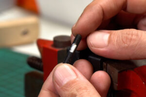
Next, we will attach a 3D print bracket to the LED panel. I will use 30 millimetre M5 screw.
In order to make it easier to lock with the screw knob, I use a metal file to flatten the screw thread to create a notch about 1 centimetre from its end. This will help secure the screw in place while tightening the knob.
Then, use a modified M4 screw to attach the bracket to the LED panel.
Wireless Switch
To control the LED light, I’m using this AC Wifi + RF smart switch. There are three different versions of this switch that come in the same package, so make sure to double-check before making a purchase to ensure you get the model that you want.

I got it from my local supplier it came with this 2-button remote control. The RF mode uses 433 Mhz, so you can also pair it with any remote that uses the same frequency, which I’ll show you how to do later in this video.
The switch is designed to connect to the wire in a hidden area, so the connector terminal is not fully covered. Since it uses AC power, I am not so comfortable to be using it in an exposed area with the original shell.

So, I designed a new shell that will mount directly to the bracket. The new shell will also rise above the back plate by about 3 millimetres to prevent the 3d print parts from making direct contact with the back plate of the LED, which can get hot during use.
To install the 3d print shell, first, insert M3 heat insert nuts to all provided holes on the bottom part of the 3D print shell. Then attach a strip of 3 millimetres of PVA foam to the bottom.
Secure the bottom part of the printed shell to the bracket with a 10-millimetre flat head M3 screw.
Next, I will remove the PCB from the original shell. Use a plastic opening tool to open the bottom cover. The cover should come off easily.
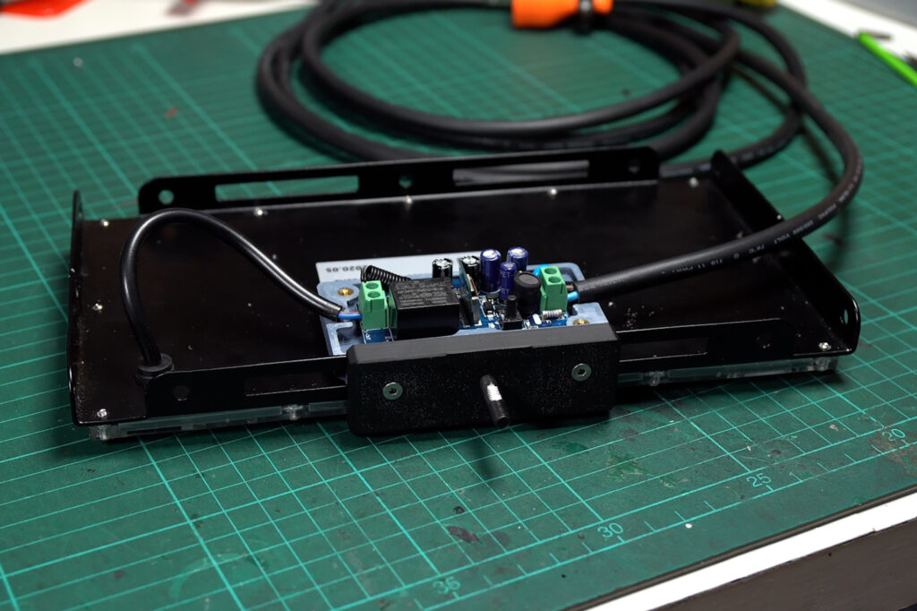
After removing the PCB, I placed it in the installed 3D print shell. The output connector terminals should face the AC input wire on the back of the LED.
Then cut the AC wire to an appropriate length, stripped off the insulation, and tinned the wires with some solder. Connected the wires to the output terminal on the PCB.
For the input, I salvaged a 2-pole AC plug wire from a broken power strip. The wire is 2 by 1 square millimetre with an outside diameter of about 7 millimetres.
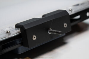
Insert the wires into the input screw terminals and tighten the connector screws.
Ensure that all wires are properly connected and secure. Insert the printed button raiser into the push button, then close the top cover and secure it with 15-millimetre M3 screws.
Please note: for the final 3D print model, I have added a slot for an M5 nut to prevent the screw from rotating.
Handle and Cable Clips
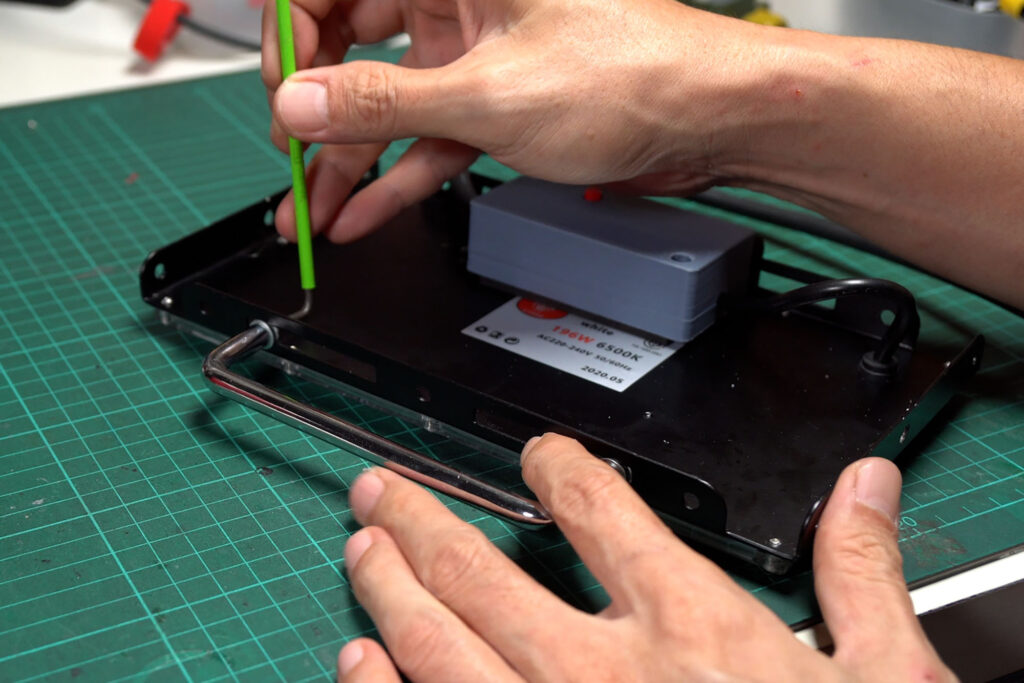
For the handle, I used a 6-inch metal drawer handle. However, you can choose any handle style that you prefer. I recommended choosing a handle that is thinner than the LED panel, which is about 1.5 centimetres thick.
Now we can mount it to the arm. Insert the M5 screw into the arm connector and secure it with the printed M4 screw knob. Then route the wire through the arm and lock it with the cable clips.

The cable clip is designed for the wire I use which is about 7 mm in diameter. If you use a different wire diameter, I have also included a STEP file that you can use to adjust the clip size accordingly. Or let me know in the comments if you need a different size of wire clip.
We need at least two clips for each section. Make sure to provide enough wire slack between each section so that the arm can move freely.
Wifi Setting
In order to control the switch with your smartphone via WiFi, you’ll need the Tuya Smart Life app.
To add the switch to the app, press and hold the switch button for at least 6 seconds. The green light will flash, indicating that the switch is in pairing mode.
Make sure your phone is connected to a 2.4 GHz WiFi network and Bluetooth is turned on.
In the Smart Life app, click “+” button on the top right to enter add device page. The app should automatically search for nearby devices.
Once the switch is found, click on “Add” and enter your WiFi network password. Wait until the app finishes adding the switch.
RF Setting
To control it with the RF remote. You have to pair it with a compatible remote control. This switch can be set to operate in three different modes, which are Toggle, Latching, and Momentary.
- Toggle Mode: you can turn the switch on and off with a single button.
- Latching Mode: you can use one button to turn the switch on and the other button to turn it off.
- Momentary mode: where the device turns on while the remote button is held down and turns off when the button is released.
But, I couldn’t get the momentary mode to work properly with this switch, with all the remote controls I have. So I’m going to skip this one.
To reset all the RF settings:
Press the button 8 times. The red indicator will flash. All the remote control data stored in the switch will be erased.
To set the switch in toggle mode:
Press the button twice the red indicator light will stay on, indicating that the switch is in a code-matching state.
Within 8 seconds, long press the remote control button you like to use, and the indicator light will go off after the code is successfully coded.
To set the switch in latching mode:
Press the button three times the red indicator light will stay on. Long press the remote control button you like to use as an “on” button. The indicator light will flash and stay on.
Then long press another remote control button that you like to set as an off switch. The indicator light will go off after the code is successfully coded.
Conclusion
Overall, I am very satisfied with my new work light. Building the custom work light can be a fun and rewarding project, especially if you have specific needs and requirements that are not met by commercially available products.
The lamp is incredibly bright and easily adjustable. The wireless control via Wi-Fi and RF remote is also very convenient. With home automation software, I can even create scripts to perform additional functions, such as turning off the light automatically after a set period.
However, it is important to note that working with AC power can be dangerous and should only be attempted by those with experience and proper safety precautions. Always follow safety guidelines and consult with a professional if you are unsure about any aspect of the project.
With that said, have fun and enjoy your new custom-built work light!
DISCLAIMER: This video and description contain affiliate links that support our channel. We are not responsible for any losses, damage, or injury in connection with the use of our content.




1 Response
[…] phone or computer. And I’ll be using the same remote control that I used in my previous DIY Wifi LED lamp […]