Introduction
The Sony NP-F (L-Series) battery is very popular for photography and videography. It’s proven itself by its existence for many decades. Because of its flexibility and capacity, it can be used with LED lights, field monitors, audio devices, cameras and etc. With a battery adaptor, the usage is even more broadened, you can use it to power any DC devices that use power around 7.4 to 9 volts. Some adaptors can output up to 12 volts.
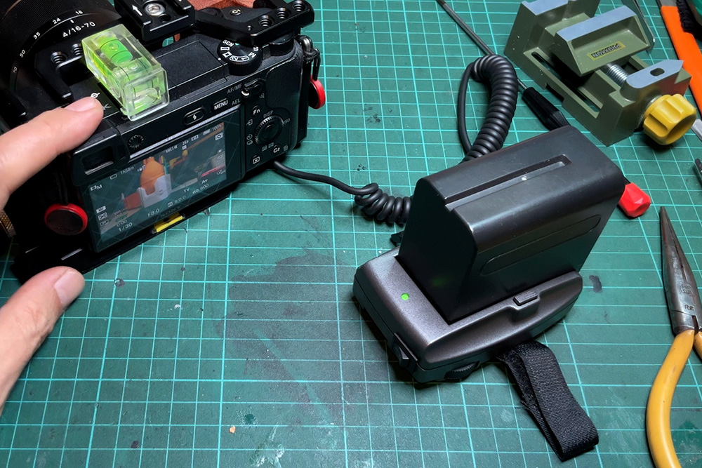
I have this old battery adaptor, that laying around in my dry cabinet for a decade. I rarely use it because most of my job is related to still image. I started using it quite a lot when I started filming a video for this channel. As you may know how fast Sony camera batteries are drained out when shooting a video.
The battery adaptor works extremely well. With the F970 battery, I can shoot entire videos with a single charge. The only problem is the adaptor has no switch. I just don’t feel comfortable when the battery is running while I’m not using it. And I hate to keep putting the battery back in and out between shooting each session.

Material List
- NP-F Battery Adaptor:
- NP-FW50 Battery Dummy: Aliexpress | Shopee Thailand
- NP-F970 Battery 7200mAh: Aliexpress | Shopee Thailand
- KCD11 Rocker Switch: Aliexpress | Shopee Thailand
Tools I use in this project
- Makita T12 Soldering Station:
- Arrowmax Mini Electric Screw Driver:
- Trumpeter Hobby Saw: Aliexpress | Shopee Thailand
- YIHUA 929D-V Desoldering Iron: Aliexpress | Shopee Thailand
- Cell Phone Opening Tools: Aliexpress | Shopee Thailand
How to Make
SUBSCRIBE TO THE CHANNEL: http://shorturl.at/gikA4
Start with opening the adapter. There are 2 screws that hold the 2 parts of the case together. Use a Phillips head screwdriver to unscrew them. Use a small flathead screwdriver to remove the fuse compartment under the adaptor.
To separate the part, use cell phone opening tools. I also have had this for a long time. I think they came with an iPod replacement battery. Start with the loosest seam near the DC outlet jack. Insert one of the tools into the seam around the corner and hold it in place to keep the 2 parts separated.

Use another tool with an angled tip. Push the tip into the largest opened seam on the side and gently slide it along the seam until the part is loose. Repeat the process on each side until the parts are separated.
I will wire the switch between the battery input and the PCB. I use a KCD11 rocker switch. The recommended cut hole from the datasheet is 13.5 millimeters by 9 millimeters.
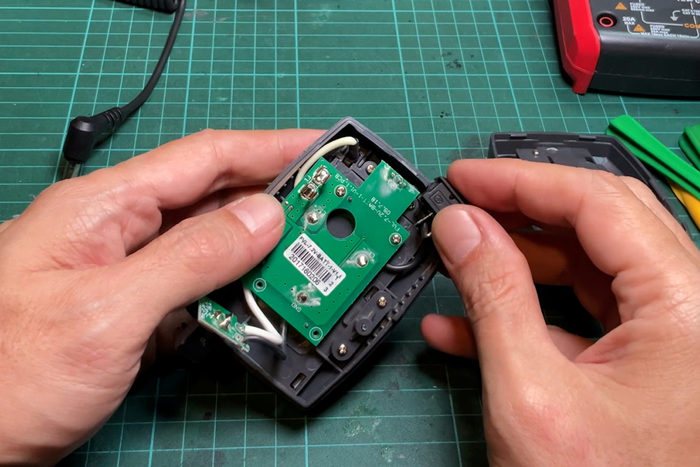
Loosens all the PCB’s screws and carefully removes the PCB from the shell. Use a wire cutter to cut the black wire and solder out the other wire.
Mark a cut hole with a marker pen. Use a utility knife to trace along the horizontal mark line. This will let the plastic crack straight along the cut line. Then I use a small hobby saw. Cut down along the vertical line. Until it touches the horizontal mark line. To be safe, I cut a little smaller than the mark.
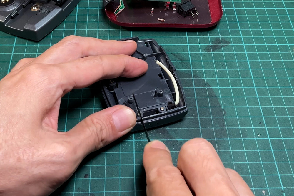
Cut some more strokes in between and use a small nose plier to remove the excess plastic. Then finished it with a coarse metal file to widen the hole until it fits the switch.
Remove the plastic piece that covers the thumb screw and use a hobby saw to trim it out about 2 millimeters. Then re-assemble it back in. Make sure that switch fits into the cut slot.
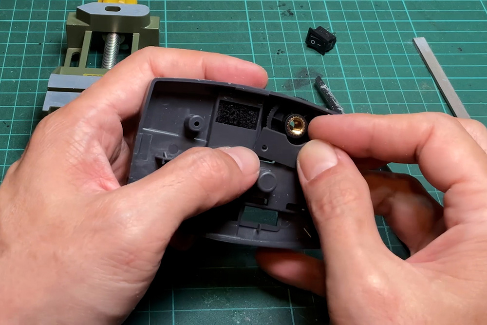
Use a soldering iron to remove the black wire from the battery pin. Replace it with a 4-centimeter black 18 AWG wire. Then weld another end to one of the switch pins. Next, connect the black wire from PCB to another switch pin. And also connect the white wire from the positive pin to the PCB.

Put back the PCB into the shell. Make sure that the LED is fit into the hole on the front. When everything is back in place, screw in and tighten all the screws. Reassemble the top and bottom shells together, starting by inserting the DC outlet jack into the slot. Then align both parts and make sure that all components inside fit into their place especially the new wire from the switch. Then carefully press on one side of the shell until it snaps. Repeat it on another side until the shell fit together. And then screw all the screws back in.
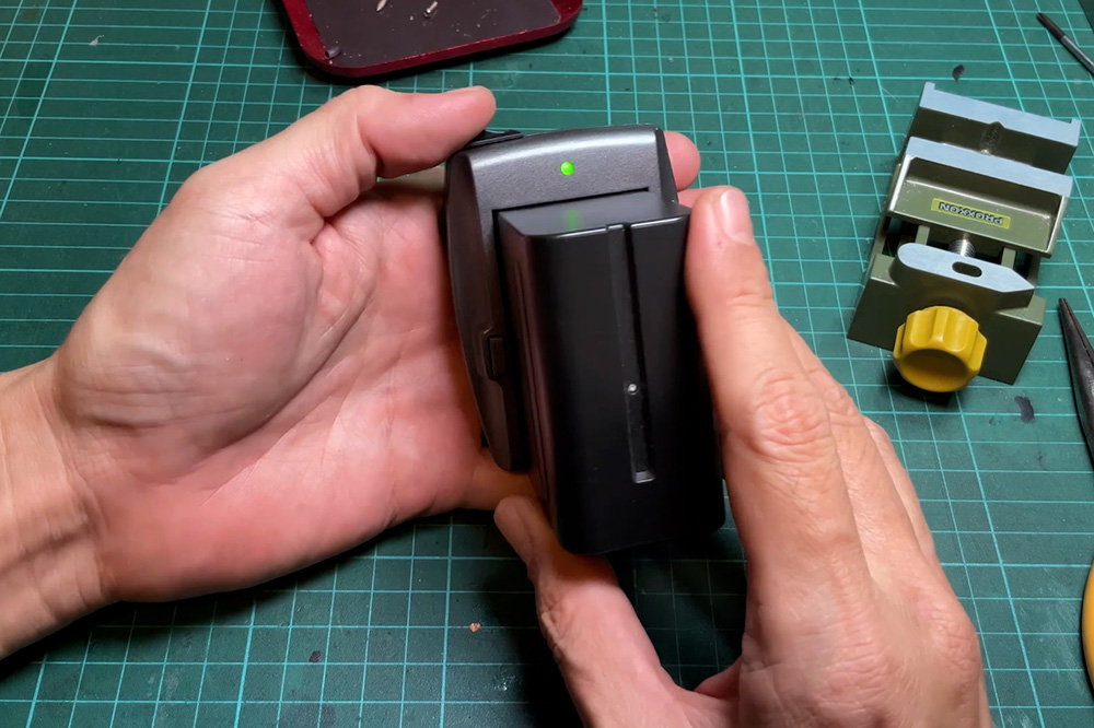
Finally, check that the switch turns to the off position (o sign). Put the battery into the adaptor slot for a test. Do not plug anything into the DC output yet. The LED on the front should turn off when you insert the battery in and turn on when you turn the switch on. Now the adaptor is ready to use.
