Introduction
The Tuya S06 Pro WiFi IR blaster is a very cheap and popular device sold under many different brands, with several internal hardware variations depending on the production batch and manufacturer.
To flash it with ESPHome firmware to use with Home Assistant, it is usually necessary to open the device and inspect the internal hardware to determine the correct configuration.
Although many S06 IR blaster teardowns already exist online, the closest match I found was this square PCB WB3S version, but it still used a different PCB layout. Because of that, I had to manually traced the PCB to confirm the correct pinout.
After some testing, I successfully got the IR transmitter, IR receiver, and built-in temperature and humidity sensor working with ESPHome. Since I could not find much information about this exact hardware version, I decided to share my findings here.
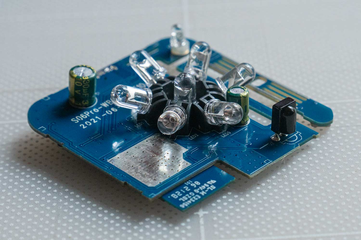
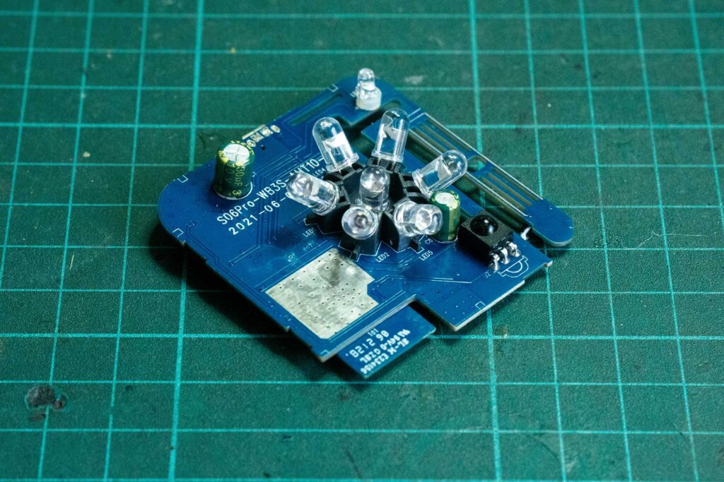
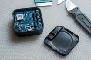
Teardown S06 Pro IR Blaster
I purchased my unit from AliExpress. However, even if you buy from the same seller, there is no guarantee that you will receive the same internal version. Externally they may look identical, but internally the hardware can be completely different. Opening the device is really the only way to know which version you have.
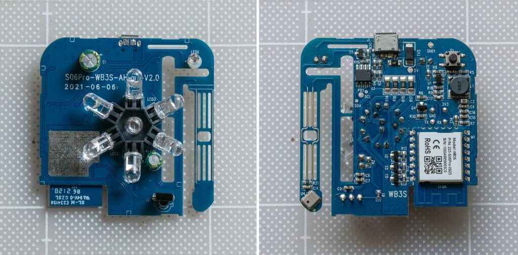
This version of S06 Pro includes:
- WB3S (BK7231T) – main Wi-Fi module
- IR transmitter (7 IR LED array)
- IR receiver
- GPIO button
- Status LED
- AHT10 sensor – temperature + humidity

Main WiFi Module
The main Wi-Fi module used in this version is the Tuya WB3S module, which is based on the Beken BK7231T MCU. The WB3S is commonly found in many Tuya smart devices and is supported by LibreTiny, allowing it to run ESPHome firmware.
The BK7231T is a low-cost 32-bit MCU with integrated 2.4GHz Wi-Fi and Bluetooth support. The WB3S module includes 2MB flash memory, 256KB RAM, runs at speeds up to 120MHz. It provides 15 GPIOs, 6 PWM channels, 2 UART interfaces, and 1 ADC, which is quite sufficient for most smart home applications.

esphome:
  name: ir-s06-pro
  friendly_name: IR s06 Pro

bk72xx:
  board: wb3s
IR Transmitter (P26)
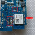
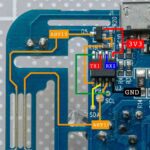
The IR transmitter is connected to P26 of the WB3S module. P26 drives four separate transistor stages (Q1–Q4) in parallel through individual base 1KΩ resistors (R10–R13).
Each transistor acts as a low-side switch with its emitter connected to GND. This design allows the circuit to drive the IR LEDs with much higher current than the GPIO pin alone could provide, helping improve IR transmission strength and coverage.
remote_transmitter:
  pin: P26
  carrier_duty_percent: 50%
IR Receiver (P8)
The IR receiver uses a three-pin IR receiver module connected to P8 of the WB3S module.
Based on its appearance and circuit design, it is likely a VS1838B or a compatible 38kHz IR receiver module, although I could not confirm the exact part number.
The output signal passes through a 10kΩ pull-up resistor (R1) to 3.3V before connecting to P8.
The module is powered by 3.3V, with the VCC line passing through multiple capacitors for power filtering and noise reduction. This helps improve signal stability and reduce interference from the nearby high-current IR transmitter circuit.
In ESPHome, the receiver is configured with the input inverted since the receiver output is active LOW.
remote_receiver:
  pin:
    number: P8
    inverted: true
  tolerance: 30%
  idle: 8ms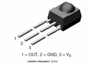
IR Receiver Upgrade
Since I mounted the module vertically on the wall and away from the AC unit, the original receiver sometimes failed to properly decode the signal and only detected it as RAW data.
To improve reception, I replaced the original receiver with a TSOP4838 module. The new module has the same pinout and operates at the same 38kHz frequency. The TSOP4838 generally provides better noise filtering and interference rejection, so it should provide more stable IR decoding and reduce invalid RAW captures.
I soldered the new receiver slightly higher than the original position and bent it upward by 90 degrees to better face the direction of the remote signal when mounted vertically on the wall.
GPIO Button (P6)
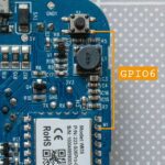
The board includes a tactile push button on the back of the device. One side of the button is connected to GND, while the other side connects directly to P6 of the WB3S module.
Since pressing the button pulls P6 LOW, the GPIO input is configured in ESPHome with both pullup and inverted enabled.
binary_sensor:
  - platform: gpio
    name: "Button"
    pin:
      number: P6
      inverted: true
      mode:
        input: true
        pullup: true
In my configuration, the button is currently used to restart the device when pressed. However, it can also be repurposed for other functions such as entering pairing mode, triggering automations, or activating IR learning mode.

Status LED (GPIO9)
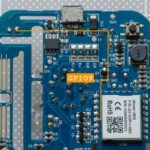
The board includes a small status LED connected to P9 of the WB3S module. The GPIO signal passes through resistor R19 before connecting directly to the LED.
The LED is used by the original firmware as a status and pairing indicator. In ESPHome, it can be configured using the status_led platform to automatically indicate device status while still allowing custom blink effects for IR transmit and receive activity.
Example uses:
- Blink while Wi-Fi connecting
- Blink on IR send/receive
- Solid ON when connected
light:
  - platform: status_led
    name: "Status LED"
    pin: P9
AHT10 – Temperature + Humidity sensor
This version of the S06 Pro includes an onboard AHT10 temperature and humidity sensor. However, unlike many ESPHome projects, the sensor is not directly connected to the WB3S module through I²C.
Instead, the AHT10 is connected to a small onboard chip labeled U3, while the WB3S communicates with U3 through the UART interface using the Tuya serial protocol.
Because of this architecture, using the standard i2c: component in ESPHome will not work for accessing the sensor. Instead, the temperature and humidity values must be read through the tuya: component using Tuya datapoints.
##### AHT10 ######
uart:
  rx_pin: RX1
  tx_pin: TX1
  baud_rate: 9600

tuya:

sensor:
  - platform: tuya
    sensor_datapoint: 101
    id: temperature
    name: "Temperature"
    unit_of_measurement: "°C"
    accuracy_decimals: 1
    filters:
      - multiply: 0.1
  - platform: tuya
    sensor_datapoint: 102
    id: humidity
    name: "Humidity"
    unit_of_measurement: "%"
    accuracy_decimals: 0
The Tuya configuration used in this project was adapted from the Avatto S06Pro IR Remote ESPHome configuration, which uses a CB3S module.
Full ESPHome Configuration
| Function | Pin |
|---|---|
| IR Transmitter | P26 |
| IR Receiver | P8 |
| Button | P6 |
| Status LED | P9 |
| Tuya UART RX/TX | TX1/RX1 |
Flashing with ESPHome
Since I had to disassembled to identify the MCU and verify the pin configuration. Flashing it directly over UART was the most convenient approach.
Because I was curious, I also tried Tuya Cloudcutter, but it did not work with this device. I did not try Tuya-Convert since I did not have the required setup for it.
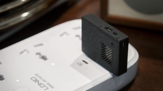
When opening the enclosure for the first time, I found a small amount of glue along the top seam. Even so, the case was still fairly easy to open without damaging it. I used a thin metal opening tool that was slim enough to fit into the seam while still rigid enough to pry the cover apart.
What you need

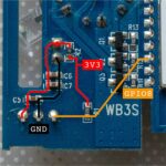
Wiring
I used standard male to female Dupont jumper wires with one end connected to the USB-to-UART adapter and male header pins soldered temporarily to the test pads on the PCB.
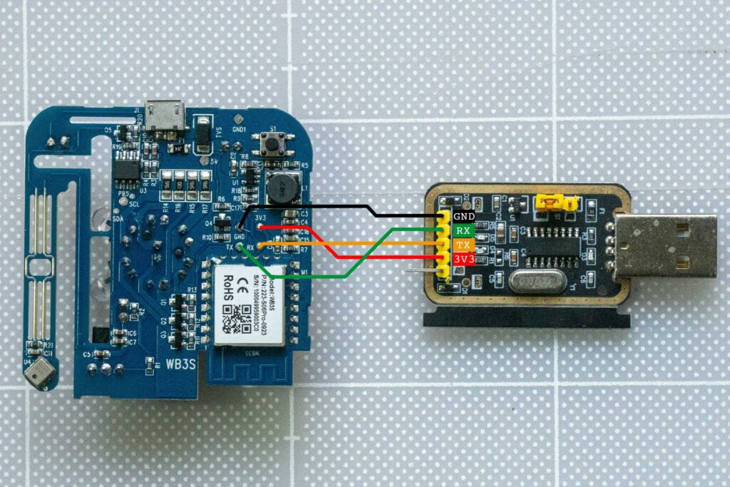
| USB UART | WB3S |
|---|---|
| 3.3V | 3V3 |
| GND | GND |
| TX | RX |
| RX | TX |
Make sure your USB-to-UART adapter is set to 3.3V mode before connecting it to the WB3S module. Using 5V may permanently damage the module.
The TX and RX pins must be crossed:
- Adapter TX → WB3S RX
- Adapter RX → WB3S TX
If LTChipTool cannot detect the device, double-check the TX/RX wiring first, as this is the most common issue.
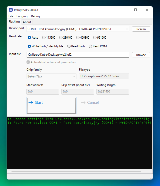
Ltchiptool GUI
For flashing the WB3S module, I used the LTChipTool GUI utility. It provides a very straightforward way to read, back up, and flash firmware for Beken/Tuya-based modules such as the WB3S.
After plugging the USB-to-serial adapter into the PC, the device should appear automatically in Device port. I is highly recommended to create a backup of the original firmware.
To create a backup:
- Open LTChipTool
- Select the correct serial port
- Connect to the device
- Choose the Read Flash option
- Save the firmware backup file to your computer
Flashing ESPHome Firmware
Once the backup is completed, flashing ESPHome firmware is quite simple.
First, compile your ESPHome firmware normally. Choose Manual Download and choose.uf2 format. The file generate by ESPHome works perfectly with Ltchiptool.
In LTChipTool:
- Choose Write Flash
- Select the downloaded
.uf2firmware file - Press Start
Enter flash mode
- Tap CEN → GND briefly to start bootloader mode.
To enter flashing mode, I used another dupont jumper wire to briefly short the CEN pin to GND while LTChipTool was waiting to start the flashing process.
Once the chip enters bootloader mode, LTChipTool should begin uploading the firmware automatically. The flashing process usually takes less than a minute.
After flashing is complete, disconnect power and reboot the device. If everything is correct, the device should boot into ESPHome and appear in Home Assistant shortly afterward.
Conclusion
Even though the Tuya S06 Pro IR blaster is a very inexpensive device, it turns out to be a surprisingly capable ESPHome platform once flashed with custom firmware.
This particular WB3S version required more work since the PCB layout and pin configuration did not match other S06 Pro teardowns I found online. After tracing the board and testing the hardware, I was able to get all major functions working correctly, including:
- IR transmitting
- IR receiving
- temperature and humidity sensing
- status LED control
- GPIO button input
Combined with ESPHome and Home Assistant, the device becomes a fully local IR hub without depending on the Tuya cloud.
Hopefully this teardown and pin mapping information helps anyone who ends up with the same WB3S hardware revision.